Airaid 510-223 User Manual
Installation instructions, Component identification
Installation Instructions
For Part Numbers:
510-223
720-472 Airaid Oiled Media Filter
511-223
721-472 SynthaMax Dry Media Filter - Red
512-223
722-472 SynthaMax Dry Media Filter - Black
513-223
723-472 SynthaMax Dry Media Filter - Blue
2007-09 Toyota Tundra 4.7L V8
2008-09 Toyota Sequoia 4.7L V8
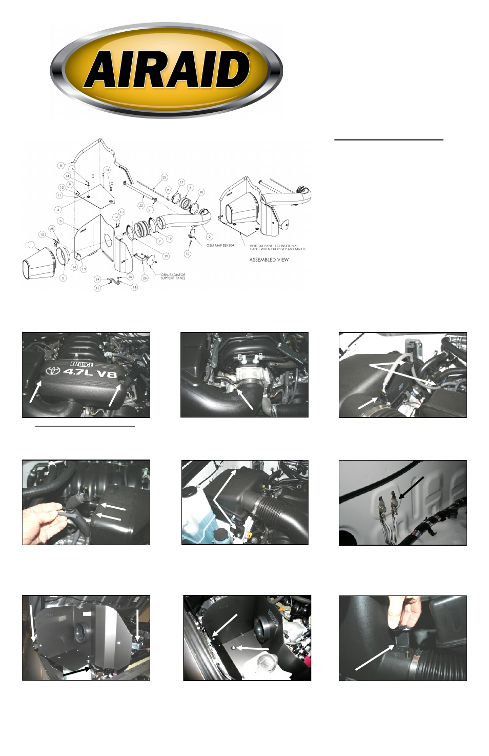
Component Identification
1.
Airaid Premium Filter
1
2.
Airaid Intake Tube
1
3.
MAF Panel
1
4.
Bottom Panel
1
5.
Filter Adapter
1
6.
Reducer Coupler
1
7.
Urethane Hump Hose
1
8.
Weather Strip 37 1/2”
1
9.
6-32x5/16” Phillips Head Screw 4
10.
#6 Flat Washer
4
11.
6-32 Keps Nut
4
12.
8-32 x 3/8” Button Head Screw 2
13.
1/4-20 x 1/2” Button Head Bolt 7
14.
1/4” Flat Washer
9
15.
1/4” Serrated Nut
4
16.
M6 x 12mm Hex Bolt
2
17.
#52 Hose Clamp
1
18.
#56 Hose Clamp
1
19.
#72 Hose Clamp
2
20.
1/8”NPT x 1/8” Barb Fitting
1
21.
#16 Speed Clamp
2
22.
1/2” x 13” Breather Hose
1
23.
1/8” x 13 Vacuum Hose
1
24.
#110 Bracket
1
25.
#140 Bracket
1
26.
#203 Bracket
1
1. Disconnect the negative battery cable.
Using a 10mm socket, remove two nuts and the
engine beauty cover. Set them to the side for now,
they will be reinstalled in step #14.
2. Using a 10mm socket, loosen the hose clamp
that secures the factory intake tube to the throttle
body.
3. A.) Squeeze the tab on the Mass Air Flow
(MAF) sensor wir ing connector and disconnect
it from the sensor. B.) Squeeze the tabs on the
bottom of the two wiring harness anchors, and
remove them from their respective anchor points.
4. Disconnect the breather hose from the back of
the factory intake tube and the valve cover. Dis-
connect the 1/8” vacuum hose from the back of
the factory intake tube and the vacuum connec-
tion on the engine. These hoses will be replaced
with Airaid hoses later in the install.
5. Using a 10mm socket, loosen the two bolts
that anchor the factory airbox to the inner fender-
well. One is on the front of the airbox, and the
other is on the rear. Pull the factory intake tube
away from the throttle body and remove the com-
plete factory intake assembly from the vehicle.
7. Assemble the Cool Air Dam panels (#3 & #4)
as shown using four 6-32 screws (#9), washers
(#10), and keps nuts (#11). Install the filter adapt-
er (#5) using three 1/4” button head bolts (#13)
and washers (#14). Install the 3 brackets (#24),
(#25), and (#26) as shown using three 1/4” bolts
(#13), washers (#14), and nuts (#15). Just snug
the bolts for now, they will be adjusted later.
6. Using a 10mm socket, remove the rear ground
anchor bolt on the passenger side inner fender-
well. Save the bolt, it will be reused in step #8.
9. Remove two Phillips head screws and remove
the MAF sensor from the factory intake tube. It
will be reinstalled in step #10.
8. Install the CAD assembly into the vehicle.
Align the hole in the bottom over the captured
nut in the fender well. Install one 6mm hex bolt
(#16), and washer (#14). Leave loose for now.
Next reinstall the factory bolt removed in step #6,
thru the bracket, into the ground anchor in the
fender well. This bolt can be tightened now.
A.
B.
#203 Bracket
#140 Bracket
#110 Bracket
Full color instructions can be viewed on our web site at Airaid.com. Use the Product Search function to find your part number, and click View Details.