Mounting location, Installation – Airmar B17-HP User Manual
Page 2
Mounting Location
CAUTION: Do not mount near water intake or discharge openings
or behind strakes, fittings, or hull irregularities.
• The water flowing under the hull must be smooth with a
minimum of bubbles and turbulence (especially at high speeds).
• The transducer must be continuously immersed in water.
• The transducer beam must be unobstructed by the keel or
propeller shaft(s).
• Choose a location away from interference caused by power and
radiation sources such as: the propeller(s) and shaft(s), other
machinery, other echosounders, and other cables. The lower
the noise level, the higher the echosounder gain setting that
can be used.
• Choose a location with a minimal deadrise angle, so the
transducer beam will be aimed at the bottom.
• Choose an accessible spot inside the vessel with adequate
headroom for the height of the housing, tightening the nuts, and
removing any insert (see the table below).
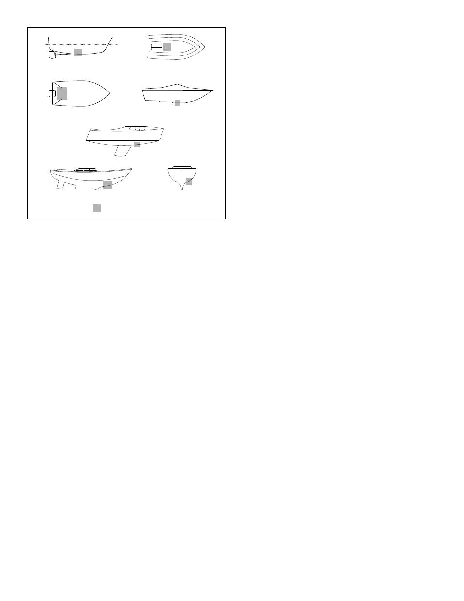
Hull Types
(see Figure 1)
• Displacement hull powerboats—Locate amidships near the
centerline. The starboard side of the hull where the propeller
blades are moving downward is preferred.
• Planing hull powerboats—Mount well aft, on or near the
centerline, and well inboard of the first set of lifting strakes to
ensure that the transducer will be in contact with the water at
high speeds. The starboard side of the hull where the propeller
blades are moving downward is preferred.
Outboard and I/O—Mount just forward of the engine(s).
Inboard—Mount well ahead of the propeller(s) and shaft(s).
Stepped hull—Mount just ahead of the first step.
Boat capable of speeds above 25kn (29MPH)—Review the
installation location and operating results of similar boats before
proceeding.
• Fin keel sailboats—Mount on or near the centerline and
forward of the fin keel 300–600mm (1–2').
• Full keel sailboats—Locate amidships and away from the keel
at the point of minimum deadrise.
Installation
Hole Drilling
Cored fiberglass hull—Follow separate instructions on page 4.
1. Drill a 3 mm or 1/8" pilot hole from inside the hull. If there is a rib,
strut, or other hull irregularity near the selected mounting
location, drill from the outside.
2. Using the appropriate size outside hull hole saw, cut a hole
perpendicular to the hull from outside the boat (see table on page 1).
Flush housing—Use a countersink tool to make a “seat” in the hull.
3. Sand and clean the area around the hole, inside and outside, to
ensure that the marine sealant will adhere properly to the hull. If
there is any petroleum residue inside the hull, remove it with
either mild household detergent or a weak solvent (alcohol)
before sanding.
Metal hull—Remove all burrs with a file and sandpaper.
Bedding
CAUTION; Be sure the surfaces to be bedded are clean and dry.
Apply a 2mm (1/16") thick layer of marine sealant around the
flange of the housing that will contact the hull and up the sidewall
of the housing (see Figure 2). The sealant must extend 6mm
(1/4") higher than the combined thickness of the hull, washer, any
spacer, and the hull nut. This will ensure there is sealant in the
threads to seal the hull and to hold the hull nut securely in place.
Stainless steel housing in a metal hull—The stainless steel
housing must be isolated from the metal hull to prevent electrolytic
corrosion. Slide the isolation bushing onto the housing (see
Figure 3). Apply additional marine sealant to the surfaces of the
bushing that will contact the hull, filling any cavities in and around
the bushing.
Installing
NOTE: Ignore any arrows on the housing, insert, and blanking plug.
1. From outside the hull, push the housing into the mounting hole
using a twisting motion to squeeze out excess marine sealant.
2. From inside the hull, slide the washer onto the housing (see
Figure 2).
B117 and P319—Also slide the spacer onto the housing and
rest it against the washer. Do not use the spacer if there is
insufficient space to tighten the nut or it is within 11mm (1/2") of
the top of the housing.
Aluminum hull less than 6mm (1/4") thick—If necessary, use
an additional rubbery, fiberglass, or plastic washer. Never use
bronze since electrolytic corrosion will occur. Never use wood
since it will swell, possibly fracturing the plastic housing.
Stainless steel transducer in metal hull—Be sure the washer
contacts the hull. Do not tighten the hull nut with the washer
against the isolation bushing, as the housing will not be firmly
installed. If necessary, sand the isolation bushing until the
washer rests against the hull (see Figure 3).
3. Screw the hull nut in place.
Plastic housing—If your housing has wrenching flats, do not
clamp tightly possibly causing the housing to fracture.
Plastic hull nut—Hand tighten only. Do not over tighten.
Metal hull nut—Tighten with slip-joint pliers.
Cored Fiberglass Hull—Do not over tighten, crushing the hull.
Wood hull—Allow the wood to swell before tightening the hull nut.
4. Remove any excess marine sealant on the outside of the hull to
ensure smooth water flow over the transducer.
2
planing hulls
Figure 1.
full keel sailboats
large displacement hulls
small displacement hulls
fin keel sailboats
Best location for transducer
Copyright © 2005 Airmar Technology Corp.
stepped hull
outboard and I/O