Testing on the water, Cable routing & connecting, Attaching the cover & speed sensor or blank – Airmar P39 TRIDUCER® Multisensor User Manual
Page 3
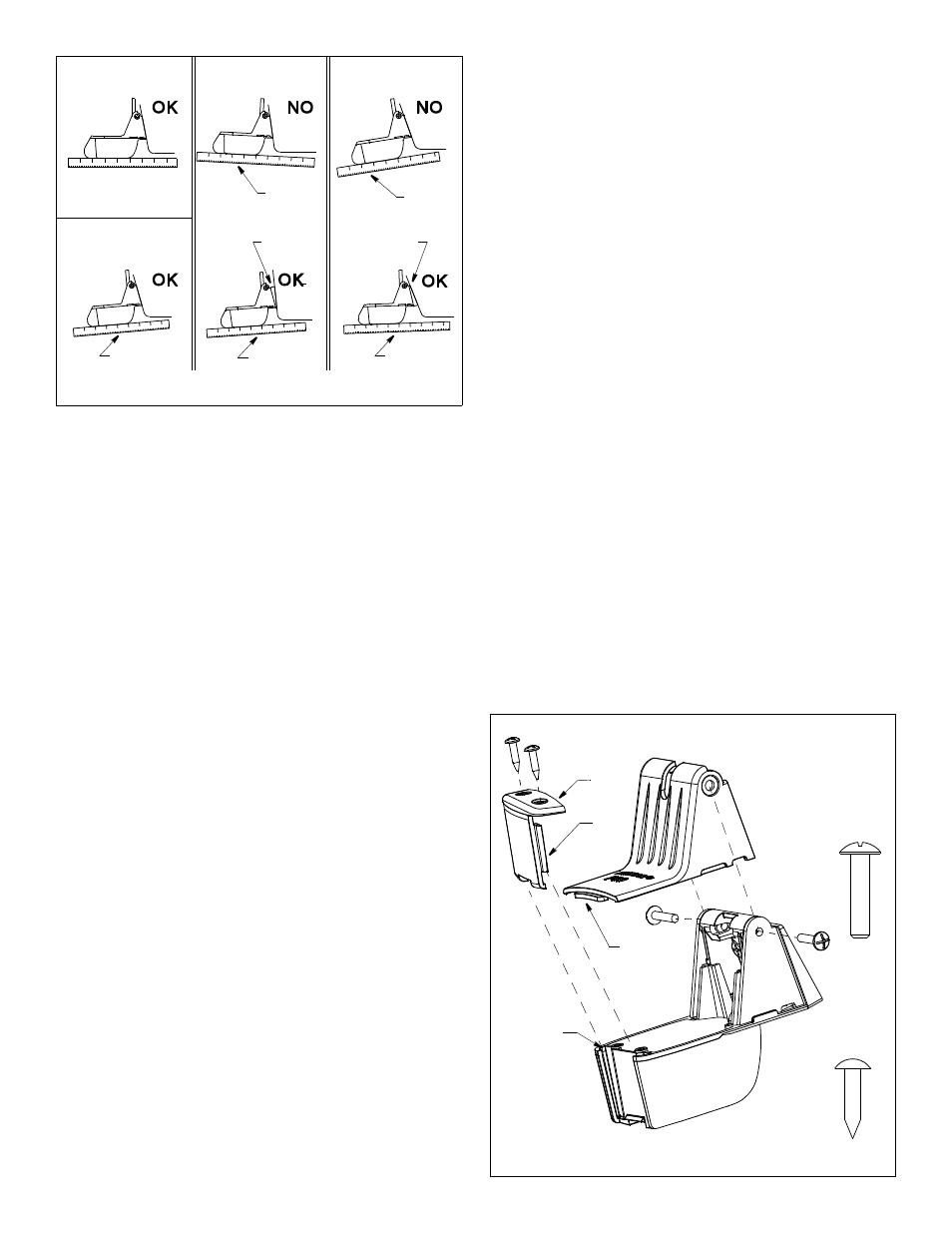
Attaching the Cover & Speed Sensor or Blank
1. Place the cover on the transducer (see Figure 7). Align the holes
in the cover with the holes in the transducer and bracket.
With speed sensor—Be sure the tab on the cover fits under the
speed sensor. This will help to lock the cover in place.
2. Insert the two machine screws capturing the nuts in the slots in
the back of the bracket. Tighten the machine screws until the
transducer will stay in the “up” (released) position unaided.
3. No speed sensor—Insert the side rails of the blank into the
channels on the back of the transducer. Slide the blank
downward. Fasten it in place with the two, #6 x 5/8", self-
tapping screws. Be sure to capture the tab on the cover. This
will help to lock the cover in place.
With speed sensor—Fasten the speed sensor to the
transducer with the two, #6 x 5/8", self-tapping screws.
Testing on the Water
1. Become familiar with your echosounder’s performance at a
speed of 4kn (5MPH).
2. Gradually increase the boat speed and observe the gradual
decline in performance due to turbulent water flowing over the
transducer’s active surface.
3. If the degradation is sudden (not gradual), identify the boat
speed at which the onset occurred. Return the boat to this
speed, then gradually increase speed while making moderate
turns in both directions.
4. If the performance improves while turning, the transducer’s
position probably needs adjustment. It is probably in aerated
water. To improve performance, try the following one at a
time in the order given.
a. Increase the transducer’s angle in the water. Review
“Compensating for Transom Angle—Shim” and see Figure 5.
b. Move the transducer deeper into the water in increments of
3mm (1/8") (see Figure 4).
c. Move the transducer closer to the centerline of the boat.
Fill unused screw holes with marine sealant.
NOTE: High-speed operation above 35 kn (40MPH) may
require less projection in the water to improve performance.
5. Calibration—To match the speed shown on the display to the
actual speed of the boat, you may need to calibrate the
instrument. Refer to your instrument owner’s manual.
Cable Routing & Connecting
CAUTION: Do not remove the connector to ease cable routing. If the
cable must be cut and spliced, use Airmar’s splash-proof Junction
Box No. 33-035 and follow the instructions provided. Removing the
waterproof connector or cutting the cable, except when using a
water-tight junction box, will void the transducer warranty.
Route the transducer cable over the transom, through a drain hole,
or through a new hole drilled in the transom above the waterline.
1. If a hole must be drilled through the transom, choose a location
well above the waterline (see Figure 4). Check for obstructions
such as trim tabs, pumps, or wiring inside the hull. Mark the
location with a pencil. Drill a hole using the appropriate size bit
to accommodate the connector.
2. Route the cable over or through the transom.
3. On the outside of the hull, secure the cable against the transom
using the cable clamps. Position a cable clamp 50mm (2")
above the bracket and mark the mounting hole with a pencil.
4. Position the second cable clamp halfway between the first
clamp and the cable hole. Mark this mounting hole.
5. If a hole has been drilled in the transom, open the appropriate
slot in the cable cover. Position the cover over the cable where
it enters the hull. Mark the two mounting holes.
6. At each of the marked locations, use a 3mm or 1/8" bit to drill a
hole 10mm (3/8") deep.
7. Apply marine sealant to the threads of the #6 x 1/2" self-tapping
screws to prevent water from seeping into the transom. If you
have drilled a hole through the transom, apply marine sealant to
the space around the cable where it passes through the transom.
8. Position the two cable clamps and fasten them in place. If used,
push the cable cover over the cable and screw it in place.
9. Route the cable to the instrument being careful not to tear the
cable jacket when passing it through the bulkhead(s) and other
parts of the boat. Use grommets to prevent chaffing. To reduce
electrical interference, separate the transducer cable from other
13
° transom angle
14
°–17° angle
Figure 6. Transducer angle adjustment
20
° transom angle
3
° transom angle
parallel
slight angle
angle
reversed
angle
too steep
shim with
shim with
taper down
taper up
slight angle
slight angle
3
NOTE: Tighten the machine
screws until the transducer
will stay in the “up” position
unaided.
Figure 7. Assembling
(exploded view)
cover
side
channel (2)
rails
tab
#6 x 5/8"
transducer
self-tapping
screw
machine
screw
ac
tu
al
si
ze
ac
tu
al
si
ze
bracket
blank
Copyright © 2003 Airmar Technology Corp.
Copyright © 2003 Airmar Technology Corp.