Airmar, Locating the converter, Preparing the cables – Airmar Analog to NMEA 0183 Speed & Temperature Data Converter User Manual
Page 2: Connecting, Completing the installation, Wiring the data converter, Wiring the display & power
Copyright © 2006 - 2010 Airmar Technology Corp. All rights reserved.
Locating the Converter
1. Select a convenient dry mounting location for the water-resistant
Data Converter. Locate it a minimum of 1m (3') away from the
display (see Figure 1). Position the converter so the bushings
are easily accessible. If the Data Converter will be mounted on
a vertical surface, face the bushings downward to avoid water
seeping into the box.
2. Hold the Data Converter at the selected location and mark the
holes for the screws. Do not fasten it in place at this time.
3. Route the sensor/instrument cable to the proposed location of
the Data Converter. Do not fasten the cable in place at this time.
4. Route the Data Converter cable from the Data Converter to the
display (and power supply on some installations).
Do not fasten the cable in place at this time.
Preparing the Cables
1. If the instrument is connected to a power source, the power must
be OFF before proceeding.
2. Allowing an extra 25 cm (10") for wiring ease, cut each cable to
length.
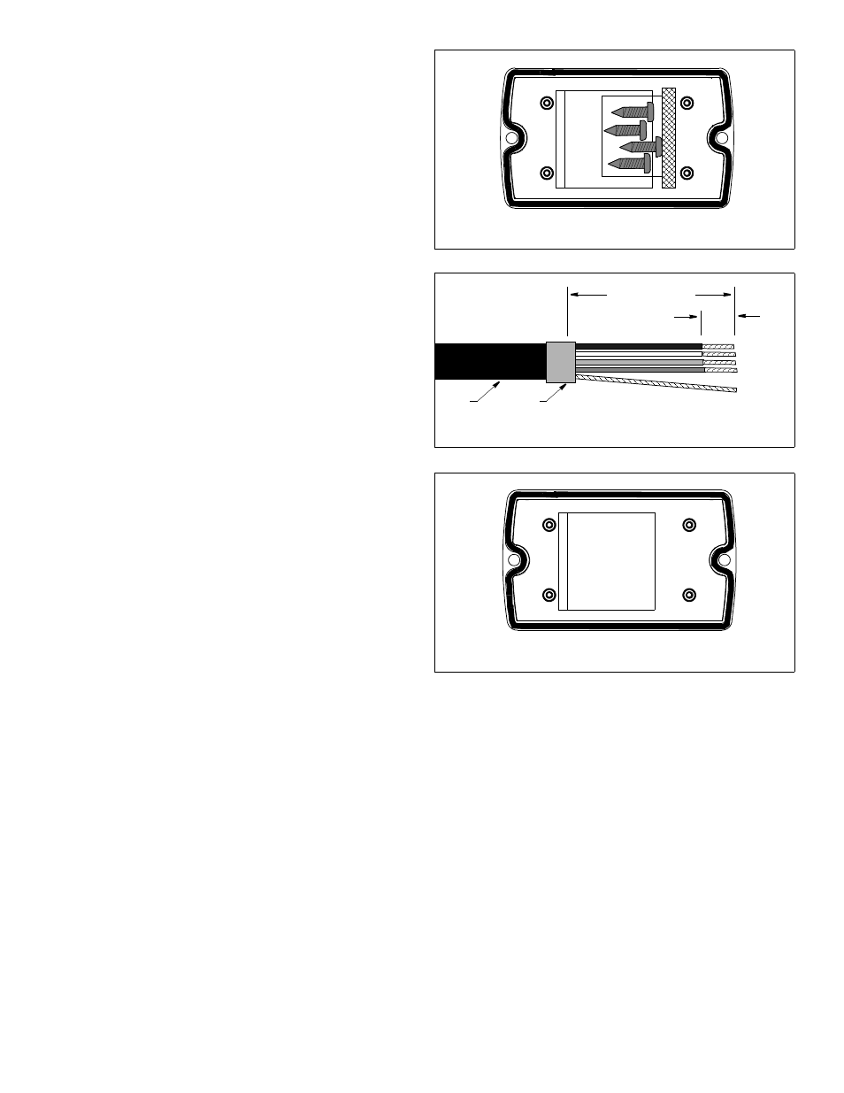
3. Remove the cover of the Data Converter (see Figure 2). Peel
the tape away from the inside and set the screws aside.
4. Push approximately 200mm (8") of the sensor/instrument cable
through the bushing of the Data Converter (see Figure 1). To
ease sliding, apply alcohol to the cable jacket.
5. Strip 60mm (2-1/2") of the outer jacket and foil shielding from
the cut ends of both the sensor/instrument cable and the Data
Converter cable (see Figure 3).
6. Strip 10mm (3/8") of conductor insulation from the end of each
colored wire in both cables.
7. Protect each cable’s foil shielding from causing a short by using
heat-shrink tubing around the jacket where the wires emerge
from the cable. The tubing must overlap the wires a minimum of
6mm (1/4").
Connecting
Wiring the Data Converter
1. From outside the Data Converter, carefully pull the
sensor/instrument cable until only 13mm (1/2") of the cable
jacket remains inside the box.
2. Connect each colored wire in turn to its corresponding terminal
on the terminal block. Insert the stripped end of the wire into the
hole in the terminal and tighten the screw using a small blade
screwdriver (see Figure 1). Be sure the stripped end of the wire
is inserted up to its insulation only. Do not include any insulation
inside the terminal. Gently tug on the wire to ensure that it is
securely fastened. Repeat this process until all the wires are
connected. Follow the color code listed on the inside of the
Data Converter cover (see Figure 4).
3. Arrange the wires neatly inside the Data Converter, being sure
that no bare wires are touching.
4. Hand tighten the nut on the bushing to make a water-resistant
seal (see Figure 1).
5. Reattach the Data Converter cover with the screws supplied.
Wiring the Display & Power
1. If there is no terminal for the bare wire (shield), cut it off flush with
the cable jacket.
2. Connect the Data Converter cable to the display. Refer to the
instructions that came with the display for connecting an NMEA
0183 speed & temperature sensor. Follow the color code below
(see Figure 1).
Black
12 VDC –
Red
12 VDC +
White
NMEA A/+
Blue
NMEA B/–
Bare
Shield
Completing the Installation
1. Using a 3mm or 1/8" drill bit, drill the holes for the screws at the
selected Data Converter mounting location.
2. Fasten the Data Converter in place using the screws supplied.
3. Fasten all the cables in place.
Pin# Function Wire Color
1 ---------- -------
2 ---------- -------
3 ---------- -------
4 Temp Brown
5 5 Volts Out Red
6 Ground Bare
7 Signal In Green
18-
474-
X
X
R
ev x
8 Temp White
Copyright © 2006 Airmar Technology Corp.
Figure 2. Inside of the Data Converter cover
Copyright © 2006 Airmar Technology Corp.
Figure 4. Wiring label inside of the Data Converter cover
Pin# Function Wire Color
1 ---------- -------
2 ---------- -------
3 ---------- -------
4 Temp Brown
5 5 Volts Out Red
6 Ground Bare
7 Signal In Green
18
-474
-X
X
R
ev
x
8 Temp White
60mm (2 1/2")
remove outer jacket
10mm
(3/8")
cable
jacket
remove
insulation
Figure 3. Preparing a cable
(sample cable shown)
heat-shrink
tubing
Copyright © 2006 Airmar Technology Corp.
AIRMAR
®
TECHNOLOGY CORPORATION
35 Meadowbrook Drive, Milford, New Hampshire 03055-4613, USA
www.airmar.com