Cable routing & connecting, Bedding, Installing – Airmar B45 User Manual
Page 3
2. Tilt the band saw table to the measured angle and secure the
cutting fence (see Figure 3).
3. Place the fairing on the table, so the cutting guide rests against
the fence. The arrow/pointed end will be pointing toward you for
installation on the starboard side of the boat or away from you
for installation on the port side (see Figure 4).
4. Adjust the cutting fence, so the fairing will be cut in about two
equal parts (see Figure 3). The section that will become the
fairing must be between 6–12mm (1/4–1/2") at its thinnest
dimension (see Figure 2).
5. Recheck steps 1 through 4. Then cut the fairing.
6. Shape the fairing to the hull as precisely as possible with a rasp
or power tool.
7. Use the remaining section of the fairing with the cutting guide
for the backing block.
Bedding
CAUTION: Be sure all surfaces to be bedded are clean and dry.
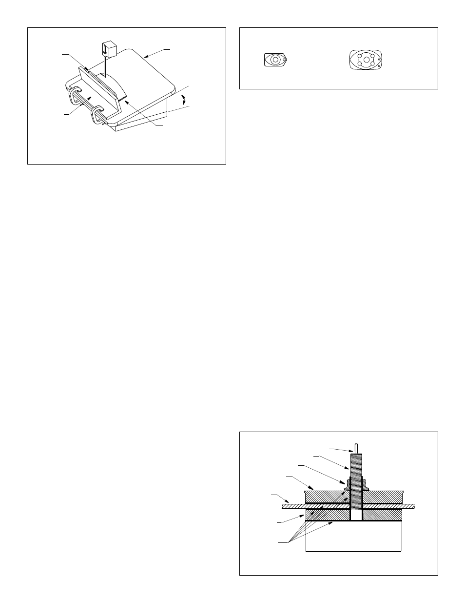
1. Remove the hull nut (see Figure 5).
2. Thread the transducer cable through the fairing (if used).
3. Apply a 2mm (1/16") thick layer of marine sealant to the surface
of the transducer that will contact the hull/fairing and up the stem.
The sealant must extend 6mm (1/4") higher than the combined
thickness of the hull, fairing and backing block (if used), and the
hull nut. This will ensure there is marine sealant in the threads to
seal the hull and hold the hull nut securely in place.
Stainless steel transducer/stem in a metal hull—Slide the
isolation sleeve over the bedded transducer stem as far down as
possible (see Figure 2). Apply a 2mm (1/16") thick layer of the
marine sealant to the outside of the sleeve.
4. Apply a 2mm (1/16") thick layer of marine sealant to the
following surfaces (see Figure 5):
• Fairing that will contact the hull
• Backing block that will contact the hull interior
• Hull nut that will contact the hull/backing block
5. Standard Fairing—Seat the transducer firmly in/against the
fairing with a pushing twisting motion. Be sure the button on the
fairing mates with the recess in the transducer housing.
Installing
1. From outside the hull, thread the cable through the mounting
hole. Then push the stem of the transducer through the hole
using a twisting motion to squeeze out excess sealant. Take
care to align the transducer with the blunt/button/arrow end
facing forward toward the bow. The long side must be parallel to
the centerline of the boat (see Figure 4).
Stainless steel transducer in a metal hull—Be sure the
isolation sleeve is between the transducer stem and the hull (see
Figure 2). However, the isolation sleeve must be below the hull
nut to prevent the sleeve from interfering with tightening the nut.
2. From inside the hull, slide the backing block (if installing with a
fairing) and the hull nut onto the cable. Seat any backing block
against the hull, being sure the arrow end faces forward toward
the bow. Screw the hull nut in place and tighten it with slip-joint
pliers (see Figures 4 and 5).
Cored fiberglass hull—Do not over-tighten, crushing the hull.
Wood hull—Allow for the wood to swell before tightening the nut.
3. Remove any excess marine sealant on the outside of the hull/
fairing to ensure smooth water flow under the transducer.
Cable Routing & Connecting
CAUTION: If the sensor came with a connector, do not remove it
to ease cable routing. If the cable must be cut and spliced, use
Airmar’s splash-proof Junction Box No. 33-035 and follow the
instructions supplied. Removing the waterproof connector or
cutting the cable, except when using a water-tight junction box,
will void the sensor warranty.
1. Route the cable to the instrument being careful not to tear the
cable jacket when passing it through the bulkhead(s) and other
parts of the boat. Use grommet(s) to prevent chafing. To reduce
electrical interference, separate the transducer cable from other
electrical wiring and the engine. Coil any excess cable and
secure it in place with cable ties to prevent damage.
2. Refer to the instrument owner’s manual to connect the
transducer to the instrument.
3
Figure 3. Cutting a Standard Fairing
cutting
guide
band saw
table
deadrise
angle
arrow/pointed end
for installation
on starboard
fence
B258, B271W, B285HW, B285M, SS258
(arrow toward bow)
marine
Figure 5. Bedding and installing
(B258 with Standard Fairing shown)
hull nut
backing
fairing
hull
sealant
stem
BOW
►
block
Figure 4. Standard Fairing orientation
BOW
►
B45
Copyright © 2005 - 2010 Airmar Technology Corp.
Copyright © 2005, 2007 Airmar Technology Corp.
Copyright © 2005- 2011 Airmar Technology Corp.
cable
transducer
(pointed end toward bow)
side of the hull
F