Preparation, Boat types (see figure 1), Headroom – Airmar B744V User Manual
Page 2: Fairing, Airmar urethane fairing, Backing block, Hull thickness
2
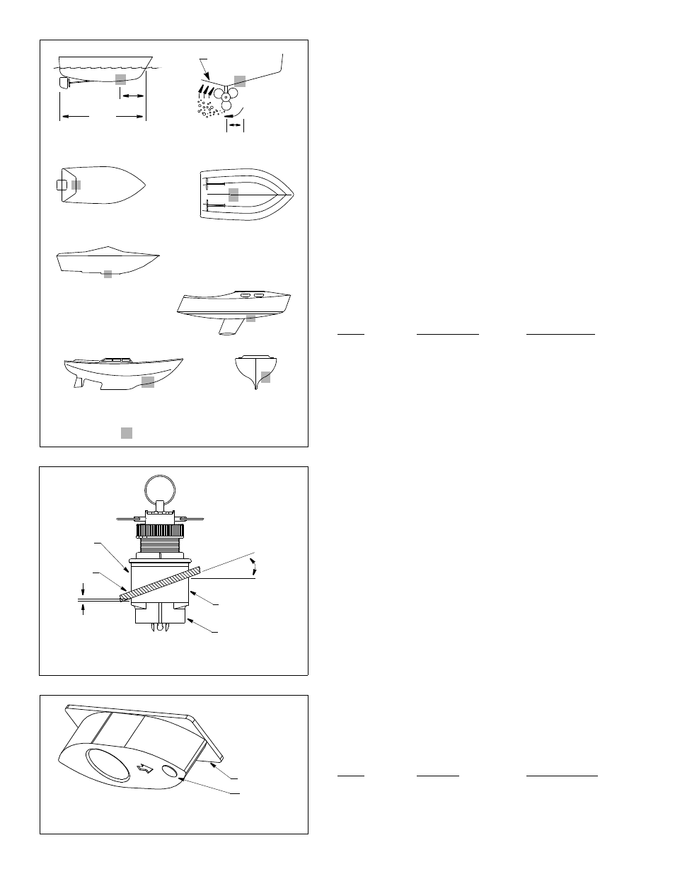
Boat Types (see Figure 1)
• Displacement hull powerboat—Locate 1/3 aft LWL and
150–300mm (6–12") off the centerline on the side of the hull where
the propeller is moving downward.
• Planing hull powerboat—Mount well aft, on or near the centerline,
and well inboard of the first set of lifting strakes to insure that it is in
contact with the water at high speeds. Mount on the side of the hull
where the propeller is moving downward.
Outboard and I/O—Mount just forward of the engine(s).
Inboard—Mount well ahead of the propeller(s) and shaft(s).
Step-hull—Mount just ahead of the first step.
Boats capable of speeds above 25kn (29MPH)—Review
multisensor location and operating results of similar boats before
proceeding.
• Fin keel sailboats—Mount to the side of the centerline and forward
of the fin keel 300–600mm (1–2').
• Full keel sailboats—Locate amidships and away from the keel at
the point of minimum deadrise angle.
Headroom
Allow adequate headroom inside the vessel for the height of the
housing, tightening the nuts and removing the insert.
Model
Min. no fairing
Min. with fairing
B744V
270mm (10
5
⁄
8
")
255mm (10")
B744VL
394mm (15
1
⁄
2
")
381mm (15")
B66V
270mm (10
5
⁄
8
")
255mm (10")
B66VL
394mm (15
1
⁄
2
")
381mm (15")
Preparation
Fairing
Nearly all vessels have some deadrise angle at the mounting location.
If the multisensor is mounted directly to the hull, the sound beam will
be tilted off the vertical at the same angle as the deadrise. A fairing is
strongly recommended if the deadrise angle exceeds 10
°
(see Figure 2).
• Orients the sound beam straight down by mounting the multisensor
parallel to the water surface
• Minimizes aerated water flowing over the transducer’s face by
mounting it deeper in the water
• Reduces drag by directing the water around the multisensor
Airmar Urethane Fairing
Made of a high impact urethane with an integrated cutting guide, an
Airmar fairing is safer and easier to cut with a band saw and shape
with hand tools than custom fairings (see Figure 3). It can be shaped
to accommodate a deadrise angle of up to 25
°. (For fairing part
numbers, see “Replacement Parts” on page 6.)
Backing Block
A backing block is used inside the hull to provide a level surface for the
hull nut to seat against. It is fabricated matching the interior deadrise
angle of the boat. After cutting an Airmar fairing, use the remaining
section with the cutting guide as the backing block (see Figure 2).
Hull Thickness
(measured perpendicular to the waterline)
Model
No fairing
Max. with fairing
B744V
10–72mm (
3
⁄
8
–2
7
⁄
8
")
26mm (1")
B744VL
35–133mm (1
3
⁄
8
–5
1
⁄
4
") 87mm (3
3
⁄
8
")
B66V
10–70 mm (
3
⁄
8
–2
3
⁄
4
")
25 mm (1")
B66VL
70–133 mm (2
3
⁄
4
–5
1
⁄
4
") 87 mm (3
3
⁄
4
")
inboard
Figure 1.
pressure waves
1/3 aft
full keel sailboat
displacement hull
(6–12")
fin keel sailboat
150–300mm
LWL
Best location for the multisensor
(Load Waterline Length)
step-hull
outboard and I/O
planning hulls
cutting guide
button
Figure 3. Airmar urethane fairing (B66V shown)
BOW
►
6–12mm (1/4–1/2")
backing
hull
fairing
multisensor
deadrise
fairing thickness
angle
slope of hull
parallel to
waterline
block
Figure 2. Deadrise angle & fairing thickness (B66V shown)
at narrowest point