Pretest speed & temperature functions, Installation, Attaching the bracket to the multisensor – Airmar P58 TRIDUCER® Multisensor User Manual
Page 2: Hole drilling, Compensating for transom angle—shims, Mounting & adjusting
Pretest Speed & Temperature Functions
Connect the multisensor to the instrument and spin the paddle-
wheel. Check for a speed reading and the approximate air
temperature. If there is no reading(s) or it is inaccurate, check the
connections and repeat the test. If there is still no reading(s) or it
is inaccurate, return the product to your place of purchase.
Installation
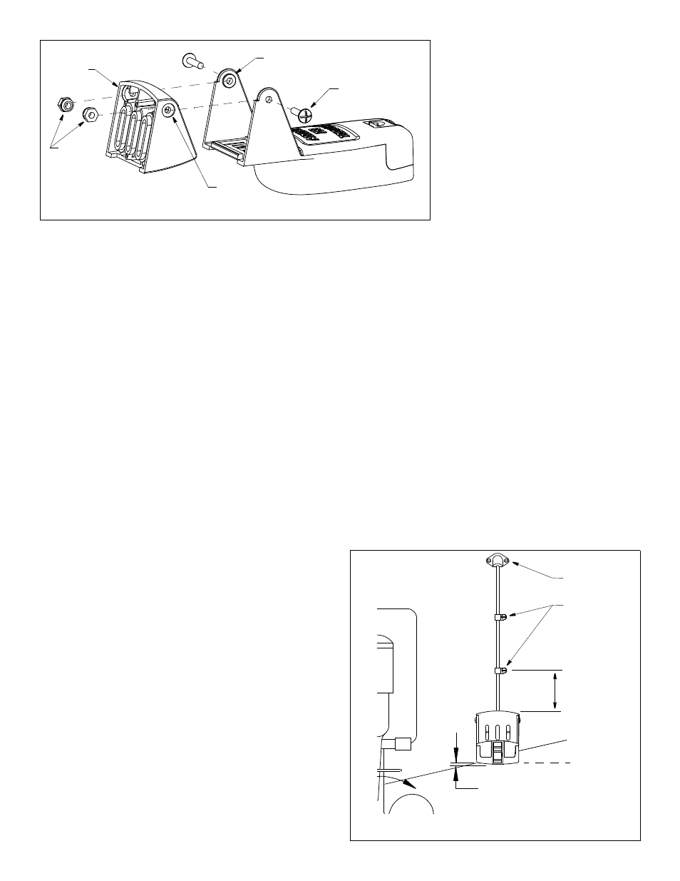
Attaching the Bracket to the Multisensor
1. Insert the multisensor’s pivot posts into the recesses on the
sides of the bracket (see Figure 3).
2. Press the two nuts into the slots in the back of the bracket.
3. Align the holes in the multisensor, bracket, and nuts. Insert the
two machine screws capturing the nuts. Tighten the machine
screws until the multisensor will stay in the “up” (released)
position unaided.
Hole Drilling
CAUTION: To prevent drilling too deeply, wrap masking tape
around the bit 22mm (7/8") from the point.
Fiberglass hull—Minimize surface cracking by running the drill in
reverse until the gelcoat is penetrated.
1. At the selected location, position the multisensor, so it projects
3mm (1/8") below the bottom edge of the transom (see Figure 4).
2. Being sure the bottom of the multisensor is parallel to the
waterline, mark the location of the screw holes with an “X” in the
center of the two outer most slots.
3. Using a 4mm, #23, or 9/64" drill bit, drill two holes 22mm (7/8")
deep at the locations indicated.
Compensating for Transom Angle—Shims
CAUTION: For boats capable of speeds above 20kn (28MPH)—
The trailing edge of the multisensor must be deeper in the water
than the leading edge. This will ensure that the paddlewheel is in
contact with the water at high speeds.
For the best performance, the transducer beam must be aimed
straight at the bottom. Since the transom of most boats is angled,
the bracket must compensate for it. Measure the transom angle of
the boat with an angle finder.
• Standard transom (13° transom angle)—The bracket is
designed for a standard 13° transom angle. The 9° shim is not
needed for this installation. If your boat is capable of speeds
above 20kn (28MPH), install the bracket with the 4.5° shim,
taper down (see Figure 5).
• Stepped transom and jet boats (3° transom angle) —Use the 9°
shim with the taper down. If your boat is capable of speeds above
2
20kn (28MPH), install the bracket with both
the 9° and 4.5° shims, taper down (see Figure
5). Install the 4.5° shim against the transom
after shaving the interfering portion of the rails
and lower bump. Place the 9° shim and
bracket assembly on top.
• Small aluminum and fiberglass boats
(20° transom angle)—Use the 9° shim with
the taper up. If your boat is capable of
speeds above 20kn (28MPH), install the
bracket with the 4.5° shim, taper up.
• Deadrise angles greater that 16°—The
hull projection will be zero.
• If you are unsure about using the shim(s)
Experiment with the shims by following the
instructions “Mounting & Adjusting.”
Mounting & Adjusting
CAUTION: Do not position the leading edge of the multisensor
lower than the trailing edge because aeration will occur.
CAUTION: Do not position the sensor deeper into the water than
necessary to avoid increasing drag, spray, and water noise and
reducing boat speed.
1. Apply marine sealant to the threads of two, #10 x 1-1/4", self-
tapping bracket screws to prevent water seepage into the
transom. Be sure the nuts are in the slots in the back of the
bracket and any shim(s) is in place (see Figure 3). Screw the
multisensor to the hull (see Figure 4). Do not tighten the screws
completely at this time.
2. Using a straight edge, sight the underside of the multisensor
relative to the underside of the hull (see Figure 5). The trailing
edge of the multisensor should be 1–6mm (1/16 –1/4") below
the leading edge.
3. Using the vertical adjustment space in the bracket slots, slide
the multisensor up or down until the bottom left corner of the
multisensor projections 0–3mm (0–1/8") below the bottom of
the hull (see Figure 4). When you are satisfied with the position
of the multisensor, tighten the two bracket screws.
Figure 3. Attaching the bracket to the multisensor
pivot post (2)
recess (2)
bracket
nuts
machine
screw (2)
slot (2)
Figure 4. Vertical adjustment and cable routing
50mm (2")
cable cover
Hull projection
0–3mm (0–1/8")
parallel to
cable clamp
waterline
Copyright © 2004 Airmar Technology Corp.
Copyright © 2004 Airmar Technology Corp.