Checking for leaks, Installation in a cored fiberglass hull, Installing – Airmar ST200 User Manual
Page 3: Cable routing & connecting
3
Installing
1. From outside the hull, push the housing into the mounting hole
using a twisting motion to squeeze out excess sealant (see
Figure 2). Align the arrow on the flange of the housing pointing
forward toward the bow and parallel to the centerline of the boat.
If the sensor is not installed on the centerline, angle the housing
slightly toward the centerline to align it with the water flow.
2. Airmar recommends a backing block or thick washer inside the
hull to distribute the force from the hull nut and provide a flat
surface to tighten against. Use a rubbery, fiberglass, or plastic
washer.
Plastic housing—Never use a wood backing block, since
swelling of the wood may fracture the plastic.
Aluminum hull less than 6mm (1/4") thick—A washer is
mandatory. Never use bronze as electrolytic corrosion will occur.
3. Screw the hull nut in place.
Plastic housing—Hand-tighten only. Do not over-tighten.
Metal housing—Tighten with slip-joint pliers.
Cored Fiberglass Hull—Do not over tighten, crushing the hull.
Wood hull—Allow the wood to swell before tightening the hull nut.
4. Check that the notch on the upper rim of the housing is aligned:
ST200—rearward toward the stern.
ST550—forward toward the bow.
5. Remove any excess sealant on the outside of the hull to ensure
smooth water flow under the paddlewheel.
6. After the marine sealant cures, inspect the o-rings on the
paddlewheel insert (replace if necessary) and lubricate them with
silicone grease or petroleum jelly. The o-rings must be intact and
well lubricated to make a watertight seal.
7. With the arrow on the top of the paddlewheel insert facing
forward toward the bow, slide it into the housing. Be sure to
engage the key in the notch. (Use a pushing twisting motion.)
Be careful not to rotate the outer housing and disturb the
sealant.
8. ST200—Align the holes of the housing and the paddlewheel
insert. Slide the retaining pin in place and attach the safety ring.
ST550—Screw the cap nut in place. Hand-tighten only. Do not
over-tighten.
9. ST550—Attach the safety wire
to prevent the insert from backing
out in the unlikely event that the cap nut fails or is screwed on
incorrectly
.
Metal housing—Wrap one end of the safety wire tightly around
the housing and twist it together with the long end. Keeping the
wire taut throughout, lead the wire straight up and through an
eye in the cap nut. Loop the wire through the pull ring and twist
it securely to itself.
Plastic housing—Attach the safety wire to one eye in the hull
nut. Keeping the wire taut throughout, lead the wire in a counter
clockwise direction. Thread it through one eye in the cap nut, the
pull ring, the second eye in the cap nut and a second eye in the
hull nut. Twist the wire securely to itself.
Cable Routing & Connecting
CAUTION: If your sensor came with a connector, do not remove it
to ease cable routing. If the cable must be cut and spliced, use
Airmar’s splash-proof Junction Box No. 33-035 and follow the
instructions provided. Removing the waterproof connector or
cutting the cable, except when using a watertight junction box, will
void the sensor’s warranty.
1. Route the cable to the instrument being careful not to tear the
cable jacket when passing it through the bulkhead(s) and other
parts of the boat. Use grommets to prevent chafing. To reduce
electrical interference, separate the sensor cable from other
electrical wiring and the engine. Coil any excess cable and
secure it in place with cable ties to prevent damage.
2. Refer to the instrument owner’s manual to connect the sensor
to the instrument.
Checking for Leaks
When the boat is placed in the water, immediately check around
the thru-hull sensor for leaks. Note that very small leaks may not
be readily observed. Do not leave the boat in the water for more
than 3 hours before checking it again. If there is a small leak,
there may be considerable bilge water accumulation after 24
hours. If a leak is observed, repeat “Bedding” and “Installing”
immediately (see page 3).
Installation in a Cored Fiberglass Hull
The core (wood or foam) must be cut and sealed carefully. The
core must be protected from water seepage, and the hull must be
reinforced to prevent it from crushing under the hull nut allowing
the housing to become loose.
CAUTION: Completely seal the hull to prevent water seepage into
the core.
1. Drill a 3mm or 1/8" pilot hole from inside the hull. If there is a rib,
strut or other hull irregularity near the selected mounting
location, drill from the outside. (If the hole is drilled in the wrong
location, drill a second hole in a better location. Apply masking
tape to the outside of the hull over the incorrect hole and fill it
with epoxy.)
2. Using the appropriate hole saw, cut the hole from outside the
hull through the outer skin only (see Figure 3).
3. From inside the hull, use the appropriate interior hole saw to cut
through the inner skin and most of the core. The core material
can be very soft. Apply only light pressure to the hole saw after
cutting through the inner skin to avoid accidentally cutting the
outer skin.
4. Remove the plug of core material so the inside of the outer skin
and the inner core of the hull are fully exposed. Sand and clean
the inner skin, core, and the outer skin around the hole.
5. If you are skilled with fiberglass, saturate a layer of fiberglass
cloth with a suitable resin and lay it inside the hole to seal and
strengthen the core. Add layers until the hole is the correct
diameter.
Alternatively, a hollow or solid cylinder of the correct diameter
can be coated with wax and taped in place. Fill the gap between
the cylinder and hull with casting epoxy. After the epoxy has set,
remove the cylinder.
6. Sand and clean the area around the hole, inside and outside, to
ensure that the sealant will adhere properly to the hull. If there is
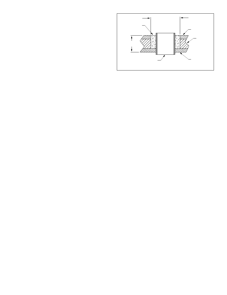
Figure 3. Preparing a cored fiberglass hull
inner skin
core
outer skin
solid or hollow cylinder
pour in
casting
epoxy
9-12 mm
(3/8-1/2")
larger than the
hole through the
hull’s outer skin
hull thickness
Copyright © 1997 Airmar Technology Corp.