Keel, Installation, Mounting directly to the hull – Airmar S61—Transom Mount User Manual
Page 2: Mounting to a transducer
2
Installation
Mounting Directly to the Hull
CAUTION: Do not position the leading edge of the sensor lower
than the trailing edge because aeration will occur.
CAUTION: To prevent drilling too deeply, wrap masking tape
around the bit 22mm (7/8") from the point.
CAUTION: Fiberglass hull—Minimize surface cracking by
running the drill in reverse until the gelcoat is penetrated.
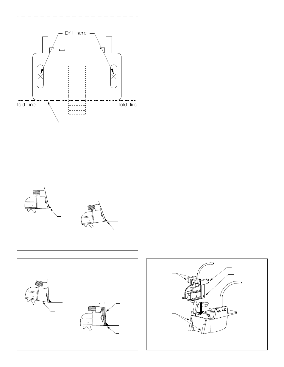
1. Cut-out the template printed on this page. Fold the template
along the fold-line (see Figure 2).
2. At the selected location, position the template so that the dotted
fold line is aligned with the bottom edge of the transom. Tape it
in place (see Figure 1).
3. Using a 4mm, #23 or 9/64" bit, drill two holes 22mm (7/8") deep
at the location indicated. To prevent drilling too deeply, wrap
masking tape around the bit 1mm (1/16") from the point.]
4. The bracket is designed for a transom angle from 13–20
°
(see
Figure 3). For other transom angles, fabricate a custom shim
from plastic, an oily wood such as teak or metal (see Figure 4).
Then, mark and drill the shim.
5. Apply a marine sealant to the threads of the two #10 x 3/4" self-
tapping screws to prevent water seepage into the transom.
Slide a flat washer onto each screw and fasten the bracket (and
any shim) to the hull.
Do not tighten the screws completely at this time.
6. Using the vertical adjustment space on the bracket slots, slide
the sensor up or down until the bottom of the bracket is flush
with the underside of the hull. Tighten the screws.
7. Fill any gap between the sensor and the hull with marine
sealant using a putty knife for smoothing. This will ensure
smooth water flowing over the paddlewheel (see Figures 3
and 4).
Mounting to a Transducer
Install the transom mounted transducer following the instructions
provided with it. Then, insert the S63 into the guide rails on the
back of the transducer. Slide it down while squeezing the tabs
inward until the shear pins reach the bottom (see Figure 5).
Release the tabs to snap the locking pins into place.
Be sure all the pins are secure.
Align with bottom
edge of transom
13° transom angle
20° transom angle
3° transom angle
Shim required
(not provided)
Figure 3. Standard transom angles
Figure 4. Shim required
Figure 2. Template
Place on starboard (right) side of boat
and fold under
marine
sealant
marine
sealant
angle too
NO
steep
shim
marine
sealant
Figure 5. Installing an S63 on a transducer
locking pins (2)
guide rails
◄
keel
tabs
shear pins (2)