Installation: fiberglass the transducer to hull, Cable routing & connecting, Dry fitting the transducer – Airmar PM260—Pocket or Keel-Mount User Manual
Page 2: Bedding & installing, Mounting location, Installing the bolts in the transducer, Fiberglassing the transducer, Tightening the nuts
Dry Fitting the Transducer
The transducer must be flush with the bottom of the hull for good
performance. Dry fit the transducer in the pocket before installing.
Bedding & Installing
(see Figure 1)
CAUTION: Be sure the surfaces to be bedded are clean and dry.
1. Cut out the template on page 4.
2. Position the template within the hull pocket and tape it in place.
3. Using the appropriate drill bits and hole saw, drill the holes
through the hull at the marked locations.
4. Sand and clean the area around the holes, inside and outside,
to ensure that the marine sealant will adhere properly. Remove
any petroleum residue with a mild household detergent or a
weak solvent such as alcohol.
5. Apply a 2mm (1/16") thick layer of marine sealant to the following
surfaces to seal the hull and hold the transducer firmly in place:
• Surface of the transducer that will contact the hull
• Cable fitting, being sure the sealant extends 6mm (1/4”) into
the hull
• Threads of the bolts
• Surface of the washers that will contact the hull
6. From outside the hull, thread the transducer cable through the
hole in the hull. Push the transducer into the mounting pocket.
7. From inside the hull, screw a nut onto each bolt. Place one
washer against each nut so that the side with the sealant will be
against the hull when installed. Then screw each bolt into a
threaded hole in the transducer. Tighten the bolts using a
torque wrench with a force not exceeding 6N-m (5ft.-lb.).
8. Lightly tighten the nuts against the hull using a torque wrench
with a force not exceeding 3.5N-m (3ft.-lb.).
9. Remove any excess marine sealant on the outside of the hull to
ensure smooth water flow under the transducer.
Installation: Fiberglass the Transducer to Hull
Mounting Location
Boat Types
(see Figure 2)
• Displacement hull powerboats—Locate amidships near the
centerline. The starboard side of the hull where the propeller
blades are moving downward is preferred.
• Planing hull powerboats—Mount well aft, on or near the
centerline, and well inboard of the first set of lifting strakes to
ensure that the transducer will be in contact with the water at
high speeds. The starboard side of the hull where the propeller
blades are moving downward is preferred.
Outboard and I/O—Mount just forward of the engine(s).
Inboard—Mount well ahead of the propeller(s) and shaft(s).
Stepped hull—Mount just ahead of the first step.
Guidelines
CAUTION: Do not mount in line with or near water intake or
discharge openings or behind strakes, fittings, or hull irregularities
that will disturb the water flow.
CAUTION: Do not mount in line with trailer rollers or bunks that
may damage the transducer’s face.
Choose a Location:
• Where the hull is flat or nearly flat, so the transducer beam will
be aimed straight down.
• Where the transducer will be in contact with the water at all times.
• Where the water flowing under the hull is smooth with a
minimum of bubbles and turbulence (especially at high speeds).
Where the transducer beam will not be blocked by the keel or
propeller shaft(s).
• Away from interference caused by power and radiation sources
such as: the propeller(s) and shaft(s), other machinery, other
2
inboard
Figure 2.
displacement hull
Best location for the transducer
stepped hull
outboard and I/O
Copyright © 2006 Airmar Technology Corp.
echosounders, and other cables. The lower the noise level, the
higher the echosounder gain setting that can be used.
• Where there is working space inside the vessel.
• CHIRP transducer—Mount in a cool well-ventilated area away
from the engine to avoid overheating.
Installing the Bolts in the Transducer
Screw a nut onto each bolt. Place one washer against each nut.
Screw the two bolts with the nuts and washers in place into the
threaded holes in the transducer. Tighten the bolts using a torque
wrench with a force not exceeding 6N-m (5ft.-lb.).
Fiberglassing the Transducer
The transducer must be professionally installed using accepted
practices. The pocket must be strong and watertight to reduce the
risk of property damage, personal injury, and/or death. The
transducer must be flush with the bottom of the hull for good
performance. Use the template on page 4 to cut the hole in the hull.
Tightening the Nuts
After the transducer has been fiberglassed to the hull, lightly
tighten the nuts using a torque wrench with a force not exceeding
3.5N-m (3ft.-lb.).
Cable Routing & Connecting
CAUTION: If the transducer came with a connector, do not
remove it to ease cable routing. If the cable must be cut and
spliced, use Airmar’s splash-proof Junction Box No. 33-035 and
follow the instructions provided. Removing the water-proof
connector or cutting the cable, except when using water-tight
junction box, will void the transducer warranty.
1. Route the cable to the echosounder being careful not to tear the
cable jacket when passing it through the bulkhead(s) and other
parts of the boat. Use grommet(s) to prevent chafing. To reduce
electrical interference, separate the transducer cable from other
electrical wiring and the engine(s). Coil any excess cable and
secure it in place with cable ties to prevent damage.
2. Refer to your echosounder owner’s manual to connect the
transducer to the instrument.
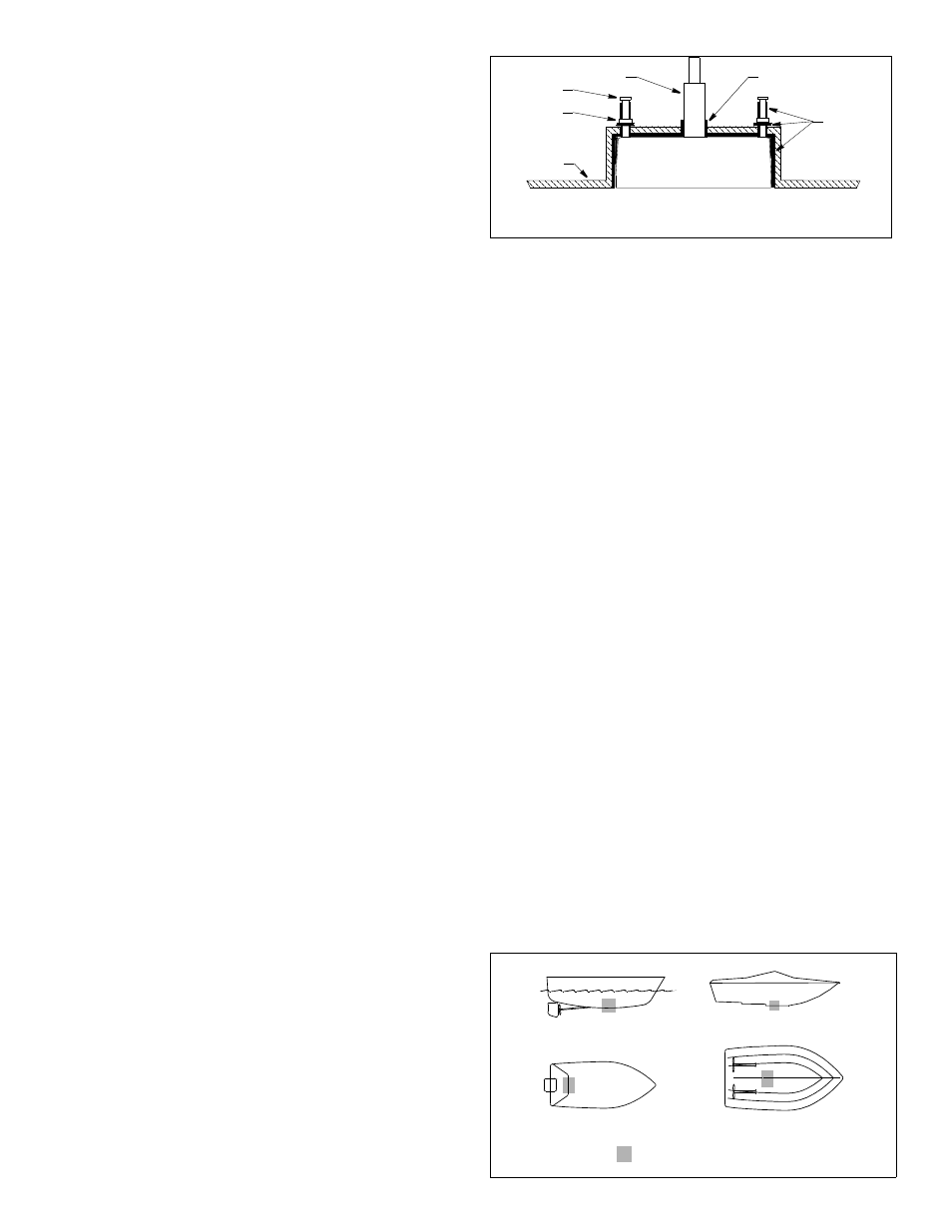
Figure 1. Installing in a pre-molded hull pocket
Copyright © 2012 Airmar Technology Corp.
transducer
hull
cable fitting
bolt (2)
nut &
washer (2)
marine
sealant
marine sealant