Connecting to the switchbox – Airmar Small Switchbox with Remote Switch–SB646 User Manual
Page 3
black
blue
blue
black
3
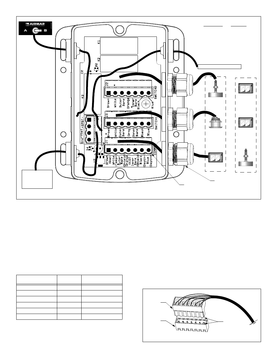
Figure 4. Wiring the switchbox
(not to scale)
compression
receptor (4)
Copyright © 2011 Airmar Technology Corp.
power
supply
fitting (3)
temperature sensor (optional)
Figure 5. Wiring & joining terminal block to receptor on PC board
Copyright © 2011 Airmar Technology Corp.
Airmar Transducer
Wire Colors
Functions
Brown
ground
White
temperature +
Outer bare
shield
Orange
Xducer ID
Inner bare
shield
Black
depth
Blue
depth +
or
1
2
2
1
Connecting to the Switchbox
CAUTION: Be sure to orient the terminal block correctly before
beginning, so the colored wires are connected to the appropriate
terminals and not in reverse order.
NOTE: For wiring ease, make connections to the terminals
outside of the switchbox.
NOTE: For Echosounder wire colors, see page 4.
NOTE: To wire an optional temperature sensor, see page 4
“Connecting an Optional Temperature Sensor” before proceeding.
Wire each cable to its designated terminal block (see Table below
and Figure 4).
1. Begin by wiring the single echosounder/transducer. Select a
seven-terminal block. Be sure to orient it correctly as it fits on the
receptor one way only (see Figure 5). Follow the color code on
the printed circuit board labeled Common (J1). Insert the
Echosounder
and 2 Transducers
Terminal Block
Transducer
and 2 Echosounders
Echosounder
Common (J1)
Transducer
Transducer A
Switch 1 (J3)
Echosounder A
Transducer B
Switch 2 (J2)
Echosounder B
Temperature (optional)
Common (J1)
Temperature (optional)
Power
J4
Power
Remote switch
J4
Remote switch
stripped end of a colored wire into the appropriate square hole
in the terminal.
2. Using a small blade screwdriver, tighten the terminal screw to
lock the wire into place. Be sure the stripped end of the wire is
inserted up to the insulation only. Do not include any insulation
inside the terminal. Gently tug on the wire to ensure it is firmly
held in place.
3. Repeat this process until all the colored wires are connected to
the terminal block.
4. Join the terminal block to the appropriate receptor on the PC
board. The block fits one way only. Push the side with the round
holes onto the pins until you hear a snap.
5. Select another terminal block and repeat steps 2 through 5. When
all the cables are connected to their designated terminal blocks, go
to “Closing & Mounting” on page 4.
rounded
edge
terminal
block
receptor