Airmar Cored Fiberglass Hull—How to Prepare Hull for Thru-Hull Housing User Manual
Airmar Sensors
hull’s outer skin to
Materials Needed
Safety goggles
Dust mask
Electric drill
Drill bit, hole saw, or spade bit for (see Figure 1):
pilot hole: 3mm
or
1
⁄
8
"
22mm (
7
⁄
8
") diameter threaded stem
exterior hole: 22mm
or
7
⁄
8
"
interior hole
a
: 35mm
or
1
3
⁄
8
"
26mm (1") diameter threaded stem
exterior hole: 26mm
or
1"
interior hole
a
: 38mm
or
1
1
⁄
2
"
43mm (1
11
⁄
16
") diameter threaded stem
exterior hole: 43mm
or
1
3
⁄
4
"
interior hole
a
: 54mm
or
2
1
⁄
8
"
51mm (2") diameter threaded stem
exterior hole: 51mm
or
2"
interior hole
a
: 60mm
or
2
3
⁄
8
"
Mild household detergent or weak solvent (alcohol)
Sandpaper
Fiberglass cloth and resin (see #5)
or
cylinder, wax, tape, and casting epoxy (see #5)
Installation in a Cored Fiberglass Hull
To
install a thru-hull sensor in a cored fiberglass hull, the core
(wood or foam) must be carefully cut and sealed. The core must
be protected from water seepage and the hull must be reinforced
to prevent it from crushing under the hull nut allowing the
housing to become loose.
Caution
: Always wear safety goggles and a dust mask.
a. The sizes given are suggestions. The optimal interior hole diameter is
effected by the hull’s thickness and deadrise angle. It must be large
enough in diameter to allow the core to be completely sealed.
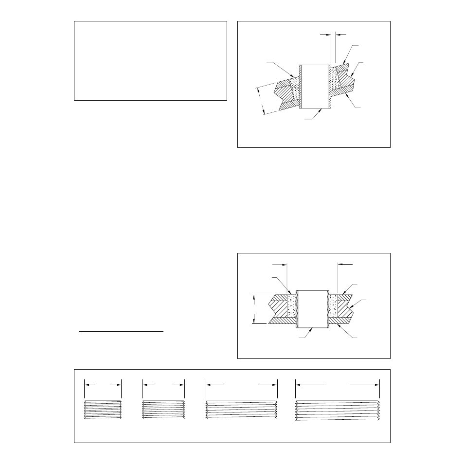
1. Drill a pilot hole from inside the hull (see Figures 2 and 3).
For installations with a fairing, drill perpendicular to the
waterline. If there is a rib, strut, or other hull irregularity near
the selected mounting location, drill from the outside the
vessel.
Note: If the hole is drilled in the wrong location, drill a
second hole in a better location. Apply masking tape to the
outside of the hull over the incorrect hole and fill it with
epoxy.
2. Using the exterior hole saw, cut a hole from outside the hull
through the
outer
skin only.
Figure 3. No fairing and minimum deadrise angle
inner skin
core
outer skin
solid or hollow cylinder
pour in
casting
epoxy
9-12 mm
(3/8-1/2")
larger than the
hole through the
hull’s outer skin
EM 17-128 re
v.
2
11/96
hull
INSTALLATION INSTRUCTIONS
Thru
-
Hull Sensor
in a Cored Fiberglass Hull
IMPORTANT
: Please read these instructions
completely before proceeding with the installation.
hull
outer skin
solid or hollow
cylinder
pour in
casting
epoxy
core
inner skin
Figure 2. For installation with a fairing
43mm (1
11
⁄
16
")
51mm (2")
22mm
26mm
Figure 1. Diameter of the sensor’s threaded stem
(
7
⁄
8
")
(1")
Dimension equal to
the thickness of the
ensure adequate
clearance