Allstar Performance ALL10270 User Manual
Tire groover with blades, Usage instructions
Allstar Performance 8300 Lane Dr., Watervliet, MI 49098
Phone: (269) 463-8000 Fax: (800) 772-2618 www.allstarperformance.com
Form
1006
Rev.
031412
Tire Groover With Blades
usaGe insTrucTions
BLADE INSERTION - Loosen the lever. The position of the lever may be adjusted by pushing the lever in and rotating it.
Insert the blade between the spacers at a position that is roughly centered in the head. Blade depth can be accurately
set by using a tire depth gauge. Avoid inserting the blade legs next to the thick black center spacer. If it is necessary
to do this in order to cut a narrower groove, the center spacer may have to be replaced periodically. Tighten the lever
firmly. Do not over tighten.
POWER LEVELS - Rubber durometer, blade size, depth of cut, and speed of cut are all variables that will affect your
power level selection. Power level 4 is the least commonly used setting. Always cut at the lowest possible power level.
Avoid smoke as this shortens blade life. A sharp blade will allow you to cut easier, faster, and with less heat. A dull or
damaged blade should be replaced. IMPORTANT: For optimum performance and longevity of the groover, use only
ALLSTAR replacement blades.
GROOVING - Place the cutting edge of the blade against the rubber. The groover will automatically activate when the
operator applies cutting pressure. Allow the front slide pads to position the tool at the proper cutting angle. Most tire
grooving is done with only the two front slide pads riding on the tire surface. The rear slide pad is only useful when
cutting across soft tires, such as some racing tires, where the give of the tire may allow the rubber to contact the rear
slide pad. The most common way to cut a zig zag groove is by an off and on action at the intersections. However, at
low power settings, these same cuts can be made with a continuous action by maintaining cutting pressure through
the intersections.
For optimum performance, the head should be cleaned daily or more often under heavy use. Remove the blade and
with the lever loosened, spray the spacers with a solvent such as a carburetor cleaner. Use compressed air to dry the
spacers and blow any loosened dirt from the head. At least weekly, spray the spacer area with solvent and use a pipe
cleaner to clean between spacers. The head is designed to be easily removed for cleaning, rebuilding, or replacement
if necessary.
CLEANING AND TOOL MAINTENANCE
HEAD UNIT REMOVAL - Unplug the groover. Remove the two brass screws located on top of the head. Turn the tool
over and use a hex wrench to remove the two socket screws holding the head unit in place. Slide head away from tool.
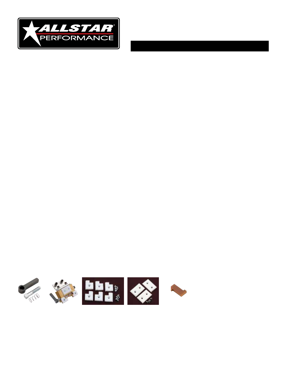
Replacement Components:
ALL99104 ........ Tension Lever Kit
ALL99105 ........ Head Assembly
ALL99106 ........ Front Pads
ALL99107 ........ Rear Pads
ALL99127 ........ Head Blade Divider
ALL99104
ALL99105
ALL99106
ALL99107
ALL99127