Allstar Performance ALL80520 User Manual
Gm mini starter, Instructions
Allstar Performance 8300 Lane Dr., Watervliet, MI 49098
Phone: (269) 463-8000 Fax: (800) 772-2618 www.allstarperformance.com
Form 1049
Page 1 of 2
Rev. 072512
GM Mini Starter
INSTRUCTIONS
Proper installation of this starter is important! Following these few steps will assure proper installation and extend the
life of the starter. When the starter is positioned correctly, the starter pinion will engage the ring gear without binding,
therefore minimizing the chance of starter pinion and/or ring gear damage.
1. MOUNTING STARTER - Make sure the mounting surface of the engine block is smooth, flat and free of paint. A good engine
ground is critical to performance of the starting and charging systems. Torque starter mounting bolts to engine to 32 ft. lbs.
2. CLOCKING STARTER - This starter comes "clocked" from the factory to fit most applications. It may be necessary to re-clock the
starter mounting block to gain adequate clearance to the oil pan, exhaust or frame. If this is required, remove the fasteners attach-
ing mounting block to starter motor and reposition the block as needed. Hold the starter block squarely against the starter-mat-
ing surface while tightening the bolts in an alternating manner. Final installation (after shimming, if necessary) will require these
fasteners to be torqued to 50 in/lbs., medium strength Loctite is also recommended.
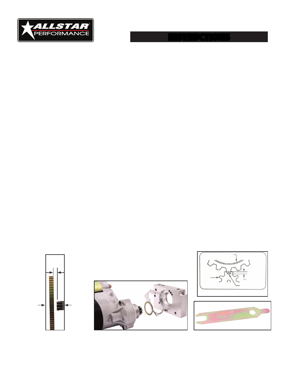
3. CHECKING STATIC PINION CLEARANCE - There should be a minimum clearance of 1/16" between the ring gear and the starter
pinion. Check this clearance in at least three locations on the ring gear as shown in FIGURE 1. If additional clearance is needed,
place included shim(s) between the starter mounting block and the starter motor as shown in FIGURE 2.
ADJUSTING STATIC PINION CLEARANCE:
1. Remove the three (3) fasteners securing starter mounting block to front of starter. (Two at front of the block; one at rear of the block.)
2. Remove the starter block by lifting it on both ends while pressing on the pinion.
3. Clean any grease or dirt from all mounting surfaces
4. Place the ring in the bearing bore.
5. Place the triangular shim on the center support housing.
6. Reinstall the block and tighten the three (3) fasteners.
4. CHECKING PINION ENGAGEMENT - Engage the pinion gear into the flywheel by carefully prying the pinion out of the starter
or by connecting a 12 Volt (+) Positive jumper wire or remote starter button to the "Switch" terminal only. (DO NOT connect bat-
tery cable to "BAT" terminal on the starter solenoid at this time) this engages the solenoid but does not spin the starter. CAUTION:
Do not leave the solenoid engaged like this for more than 30 seconds at a time as the solenoid will overheat. Insert a wire gauge
to check for proper clearance between the ring gear and starter pinion shown in FIGURE 3. Clearance measured from the valley
of the starter pinion to the tip of the ring gear tooth should be 0.020" to 0.035". (NOTE: A #1 standard paper clip is usually about
0.035" in diameter and makes an easy tool.) Check clearance at least three places on the ring gear. If the clearance is too small, add
shim shown in FIGURE 4, one at a time between the starter mounting block and the engine block to gain adequate clearance. In
many installations, no shims are necessary. If clearance is too great, machining of the starter mounting block may be required.
FIGURE 2
FIGURE 3
RING GEAR
PINION
INSERT WIRE
GAUGE HERE
(0.020-0.035)
FIGURE 4
PLEASE NOTE: After releasing the solenoid, the pinion may STAY ENGAGED in the ring ear until the engine is started. This
is normal for gear reduction starters and does NOT require shimming to correct.
1/16"
OR
MORE
FIGURE 1
Ring
Gear
Starter
Pinion