Atlantic Water Gardens TRION2 User Manual
Page 4
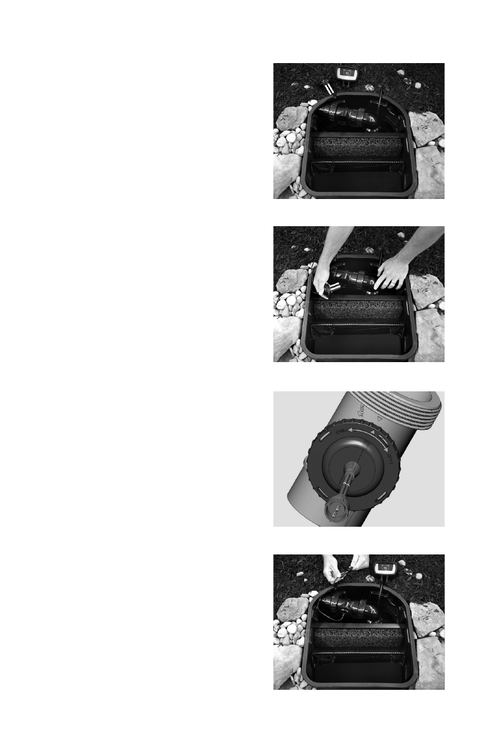
Install the electrodes into the electrode
chamber. The electrode body has a double
O-ring to ensure a watertight seal. Please
inspect the electrodes before installation to
verify that both O-rings are in place. (Fig. 4)
Align the arrow on the top of the electrodes
with the “align” arrow on the electrode
housing. Push downward on the electrodes
and turn in the “close” or clockwise direction
until the next arrows align or the electrode
arrow points directly down the centerline of
the Ionizer outlet. (Fig. 5)
Mount the control panel in the desired
location. The control panel is weatherproof,
but should be mounted above the ground on
a wall or post. Ensure that the power cord
is within reach of a properly grounded GFCI
outlet, and that the outlet cord can reach the
electrodes. Connect the outlet cord to the
electrodes and the power cord to the supplied
12 volt AC transformer using the quick-connect
attachments. (Fig. 6)
In-Line Installation:
The Triton Ionizer can be easily retrofitted to
any existing water feature. A standard 2”
female fitting (not included) is required to
complete installation. If installing within a
pump vault or skimmer, where the electrode
chamber can be removed with the pump and
check valve, a 2” coupling can be used. If
installing in-line, outside the pump vault or
skimmer, the use of a 2” union or Fernco is
recommended. Attach the 2” coupling, union
or rubber Fernco to the spigot end of the
electrode chamber. Measure the assembled
electrode chamber to determine the length
of waterfall feed line to be removed. (Fig. B)
Note: If installing the Triton Ionizer into a
system using a waterfall feed line smaller
than 2”, all reducing bushing must be attached
before measuring the electrode chamber.
Measure the feed line and mark the
appropriate length section of waterfall feed
line to be removed. Using a hacksaw, PVC
saw or PVC cutters; remove the necessary
section of the supply line, making sure to
leave at least 1½” of pipe at either end to
make the appropriate connections. (Fig. C)
4
Fig. 4
Fig. 3
Fig. 5
Fig. 6
Installation with TR215CV: