Bestobell Steam DT711 Series Disc Trap User Manual
Please read these instructions, Ideal installation schematic, Dt711 series
3170 Wasson Road • Cincinnati, OH 45209 USA
Phone 513-533-5600 • Fax 513-871-0105
[email protected] • www.bestobellsteamtraps.com
DT711 Series
Installation & Maintenance Instructions for
Bestobell Steam DT711 Series Traps
Warning: Bestobell Steam products must only be used, installed and repaired in accordance with these Installation
& Maintenance Instructions. Observe all applicable public and company codes and regulations. In the event of leak-
age or other malfunction, call a qualified service person; continued operation may cause system failure or a general
hazard. Prior to servicing equipment, disconnect, shut off, drain and/or bypass all pressurized fluids.
Please Read These Instructions
The Bestobell DT711 Series will provide you with long, trou-
ble-free service if it is correctly installed and maintained. A
few minutes of your time spent reading these instructions
may save hours of trouble and downtime later.
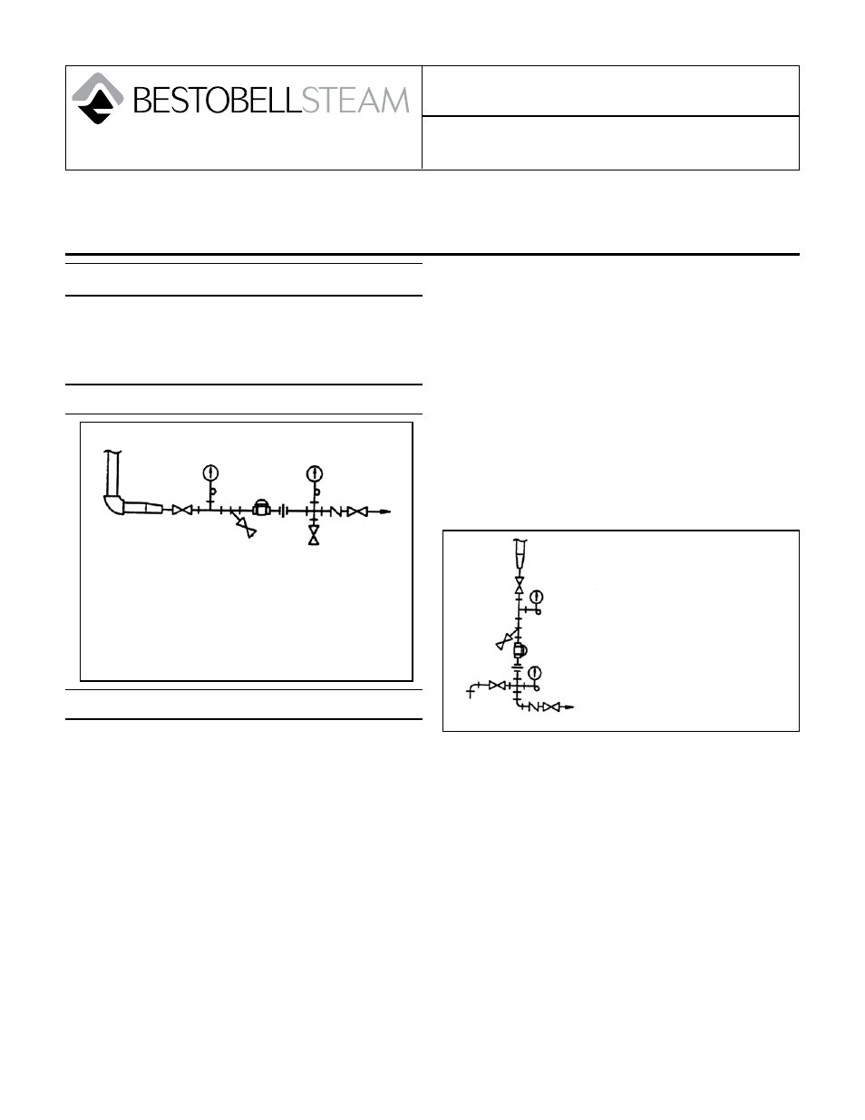
Ideal Installation Schematic
Ideal Installation Schematic
To protect the trap from grit, scale, thread chips
1.
and other foreign matter, all pipe lines and piping
components should be blown out and thoroughly
cleaned before the trap is installed.
In preparing threaded connections, care should
2.
be exercised to prevent pipe sealing compound
from getting into pipe lines. Pipe sealing compound
should be used sparingly, leaving the two end
threads clean. Bestobell uses, and recommends,
thread sealer Teflon ribbon.
The trap may be installed horizontally or vertically
3.
with discharge downward. The preferred installation
is in the horizontal position as close as possible to
the equipment being drained. Whenever possible,
position trap below unit being drained.
Piping should be the same size as the trap connec-
4.
tion. To avoid excessive back pressure, discharge
piping should be the same size on short runs, for
longer lines, use one size larger.
The piping should be sloped to and from the trap.
5.
Use eccentric reducers in horizontal lines to avoid
water build-up at the bottom of the pipe.
A full-ported shutoff valve upstream is recommend-
6.
ed to allow isolation for servicing. A shutoff valve
downstream will protect against back flow from the
return line during servicing.
A strainer should be installed with a blowdown valve
7.
immediately upstream of the trap to protect it from
grit, scale, and other foreign matter.
A single union connection on inlet or outlet is re-
8.
quired to allow removal from the line if necessary.
A test valve outlet and pressure gauges should be
9.
provided to check trap operation where condensate
discharge is piped to a return line.
For freeze protection, trap should be installed verti-
10.
cally with discharge downward, as shown above.
Discharge as close to drain connection as practi-
cal and discharge to atmosphere directly through
a short pipe. A vacuum breaker upstream may be
required to provide complete drainage.
7
1
9
2
6
5
8
3
4
6
1
Shutoff Valve
1.
Test Valve
2.
Blowdown Valve
3.
Strainer
4.
Pipe Union
5.
Pressure Gauge (with Snubber
6.
Pipe Eccentric Reducer (if
7.
required)
Bestobell DT711 Disc Trap
8.
Check Valve
9.
6
9
1
2
8
4
3
6
1
Shutoff Valve
1.
Test Valve
2.
Blowdown Valve
3.
Strainer
4.
Pipe Union
5.
Pressure Gauge (with Snubber)
6.
8. Bestobell DT711 Disc Trap
9. Check Valve