Bestobell Steam PT Series Float & Thermostatic Trap User Manual
Page 2
3170 Wasson Road • Cincinnati, OH 45209 USA
Phone 513-533-5600 • Fax 513-871-0105
[email protected] • www.bestobellsteamtraps.com
Bulletin IM-PT-0615
1. Remove drain plug (8) to empty condensate from
trap.
2. Trap does not need to be removed from piping to
perform maintenance procedures. Remove cover
bolts from around the flange. Lift off the cover (2)
of the steam trap, which will bring with it all internal
working components.
3. Wipe out or rinse out interior of steam trap body (1).
4. Dismantle the valve mechanisms by removing the
bracket pivot pin and pulling away the float lever as-
sembly (3).
Inspect valve seat (5) and plug for any scale build-
up, worn or pitted sealing surfaces. If slight evidence
of above conditions exist, then the seating surfaces
can be touched up by lapping the plug (8) to the
seat (5) by hand with a very fine grinding compound
paste.
If the surfaces are badly pitted or worn or do not
clean up by above method, replace the seat and
plug.
C
B
1
2
3
4
5
6
7
8
9
10
5. If the seat (5) has been removed, inspect its seating
surface and clean the old gasket material completely
away. Replace seat gasket as required.
6. Inspect the float mechanism (3) linkage points for
wear, especially at pivot points and pivot pins. Re-
place if worn.
7. Inspect flat ball for corrosion, pitting splits or pin-
holes. Replace if there is any evidence that the float
may leak. Replace if the float is dented or crushed.
8. Inspect the air vent mechanism (6) for fatigue cracks,
corrosion and worn seats. Replace if it shows any
sign of wear of if there is any doubt about its condi-
tion.
9. After cleaning all gasket surfaces, reassemble trap
in reverse order. Lubricate the lever pivot points
with small amounts of graphite paste. An anti-seize
compound on all threads will aid in the disassembly
of the trap at a later date.
10. Before putting cover and attached mechanisms
back into the trap body, make sure linkages move
smoothly and freely. Also, check that the valve plug
seats properly on the seat (5).
11. Replace cover assembly (2) into the trap body (1)
using a new body gasket. Tighten bolts evenly, then
test for any leaks after replacing drain plug (8).
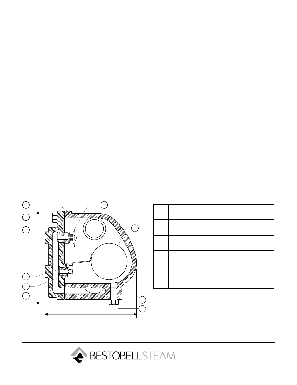
No.
Part
Material
1
Body
Cast Iron
2
Cover
Cast Iron
3
Ball Float & Lever Assembly
Stainless Steel
4
Bracket
AISI 304
5
Valve Seat
Cr. Steel
6
Air Vent
Stainless Steel
7
Gasket
Non CAF
8
Drain Plug
Carbon Steel
9
Bolt
High Tensile
10
Gasket
Non CAF
Warning:
Be sure that there is no pressure in the trap before loos-
ening any fittings or joints. Shut off the steam supply and
permit the trap to cool to prevent rupture or distortion
of the disc. Isolate connection to condensate system as
required.