2 mixed irf topology, Mixed irf topology – H3C Technologies H3C S5820X Series Switches User Manual
Page 6
2-1
2
Mixed IRF Topology
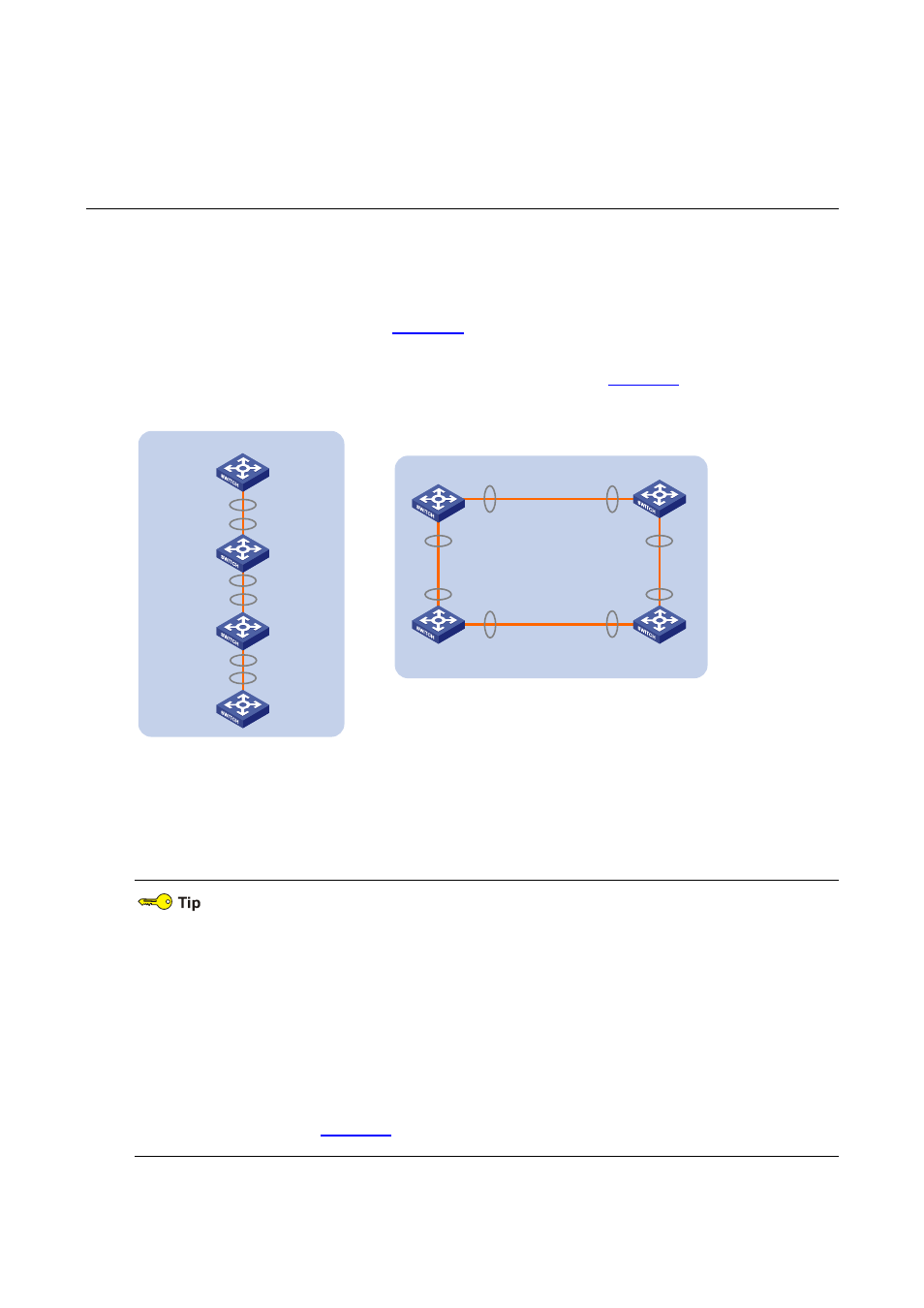
An IRF typically adopts daisy chain connection or ring connection:
z
Daisy chain connection: Given a device, its IRF port 1 is connected to IRF port 2 of another device,
and its IRF port 2 is connected to IRF port 1 of a third one; devices are connected to form a single
straight connection, as shown in
.
z
Ring connection: Given a device, its IRF port 1 is connected to IRF port 2 of another device, and its
IRF port 2 is connected to IRF port 1 of a third one, as shown in
.
Figure 2-1 Physical connections of IRF
IRF
Ring connection
Slave Slave
Master
IRF- Port1
IRF- Port2
IRF- Port1
IRF- Port2
IRF- Port1
IRF- Port2
Daisy chain connection
IRF
Master
Slave
IRF- Port2
IRF- Port2
IRF- Port1
IRF- Port1
Slave
IRF- Port2
IRF- Port1
IRF- Port1
IRF- Port2
The orange lines in the figure represent IRF cables. The IRF cable can be composed of either one
physical cable or multiple physical cables.
z
A ring connection is more reliable than the daisy chain connection. In a daisy chained IRF, the
failure of one link can cause the IRF to split into two independent IRF systems; where the failure of
a link in a ring connection result in a daisy chain connection, not affecting IRF services.
z
You are recommended to use the ring topology to establish an IRF and use the IRF aggregate
ports for connection, thus to increase the connection bandwidth among member devices and
provide the link redundancy backup function. As the S5820X series switches are 10-Gigabit
Ethernet switching products, you are recommended to use the S5820X series as the upstream
devices and make an S5820X switch be elected as the master in the IRF by configuring member
priorities, as shown in
.