Frame rear connections, Grounding lug, Ac mains connection and fusing – Grass Valley 7600REF Installation User Manual
Page 13: Module cabling
7600REF — Installation and Safety Manual
13
Frame Rear Connections
Frame Rear Connections
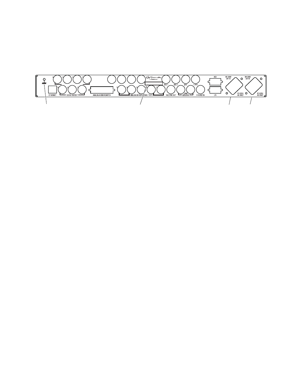
The rear backplane of the 7600REF Reference Generator is illustrated in
.
Figure 1. 7600REF Rear Backplane
Grounding Lug
The unit is provided with a single 4 mm (0.16 in.) ground lug on the far left
of the rear panel. Incoming mains ground from the IEC connector is inter-
nally bonded to both the chassis and technical 0V to meet safety require-
ments and performance specifications. The stud allows the addition of an
ground strap, if required, for rack installations.
AC Mains Connection and Fusing
CAUTION The power supply cord is used as the main power disconnection device.
Ensure that the socket outlet is located/installed near the equipment and is
easily accessible.
ATTENTION Le cordon d’alimentation est utilise comme interrupteur général. La prise de
courant doit être située ou installée à proximité de l’équipement et être facile
d’accès.
The power supplies within the unit are a switch mode design and are
auto-sensing to handle a wide input voltage range. See
Each 7600REF model is fitted with two AC mains power supplies. Each
power supply has its own dedicated IEC mains plug on the rear of the unit.
You should receive the correct line cord for your line standard in the ship-
ping box.
Module Cabling
Cabling of module BNCs and Sub-D connectors depends upon the frame
model type and what modules are included with the model. Refer to the
7600REF Instruction Manual for details on cabling the required connections.
Grounding Lug
AC/Mains In
AC/Mains In
Model #, Part #, and Serial #