Functional description, Input section, Output section – Grass Valley 8911 User Manual
Page 8
2
8911 Instruction Manual
8911 AES/EBU Reclocking Distribution Amplifier
Functional Description
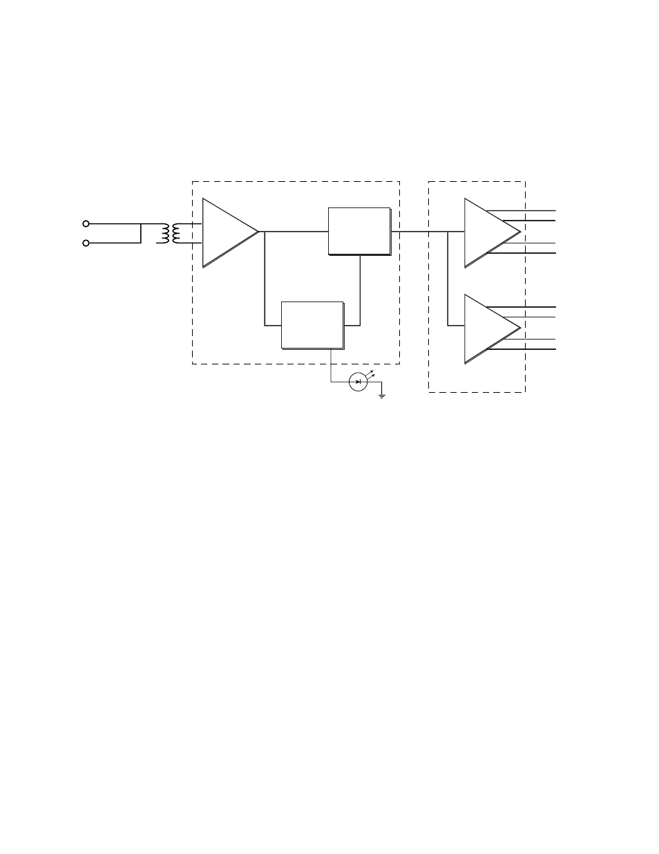
The 8911 has one loop-through, high impedance input and produces eight
75-Ohm outputs. The AES/EBU data is reclocked by means of a phase-
locked-loop. Refer to
while reading the following description.
Figure 1. 8911 AES/EBU Reclocking DA Block Diagram
Input Section
The input channel is loop-through and is not terminated (the differential
input is high impedance). The input signal comes from the 50-pin con-
nector, P1, and feeds a transformer, T1. Transformer coupling on the input
eliminates common mode noise. The output side of the transformer feeds
the differential line receiver of AES/EBU receiver U3.
The AES/EBU receiver reclocks the data for its AES/EBU data stream. The
mode pins 17, 18, 23 and 24 are set to pass the entire AES3 signal with the
preamble. The receiver has an incoming audio sample frequency range of
25 KHz to 55 KHz.
Output Section
After it is reclocked, the serial data is routed to a quad EIA-485 line driver,
U4. The line driver chip drives eight output lines.
Phase
Locked
Loop
Input Section
AES/EBU Receiver
U3
Output Section U4
Differential
Line Rx
Output
Line Driver
Output
Line Driver
AES
Outputs
T1
0544_00
Reclocker
Loop-through
AES Input
Lock LED