Adjustments and indicators – Grass Valley 8980TLS User Manual
Page 13
8980TLS Instruction Manual
7
Adjustments and Indicators
Adjustments and Indicators
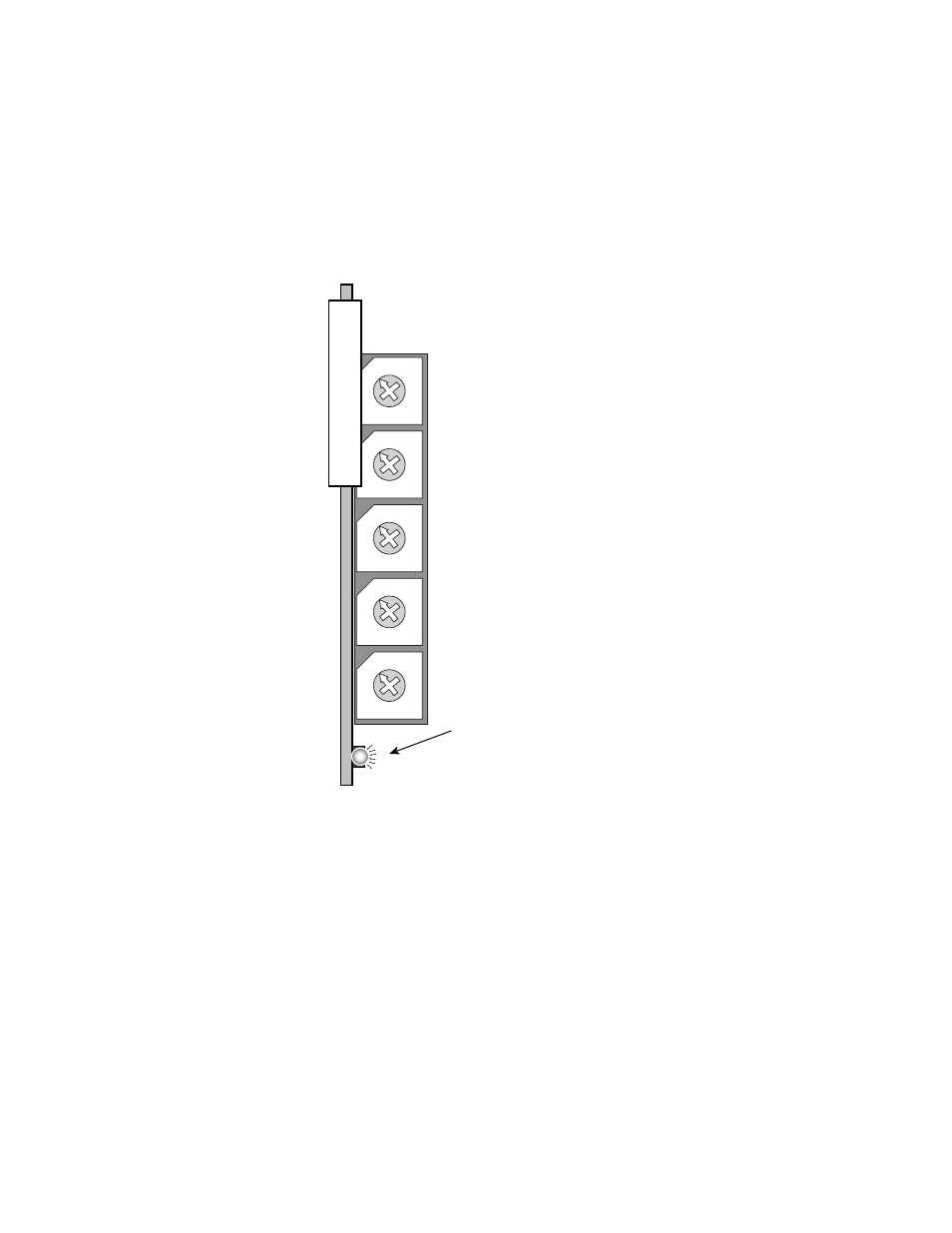
The 8980TLS output signal timing is adjusted relative to the input signal
using switches provided on the front panel (see
). The green LED
on the front of the module indicates the presence of an NTSC reference
input signal.
Figure 6. Timing Adjustment Rotary Switches and Signal Present LED
To adjust the timing of the outputs relative to the input reference, use the
front panel switches (SW1 through SW5). There are five front panel
switches. SW1 is at the top and provides output timing control in 3.54 mil-
lisecond steps. SW2 provides 221 microsecond steps. SW3 provides 13.5
microsecond steps. SW4 provides 864 nanosecond steps and SW5 (bottom
switch) provides 54 nanosecond steps.
The timing of the output vertical interval first broad pulse will match the
timing of the input first broad pulse in 720P with the switches set to 4, B, 5,
E, and 0 (read from top to bottom). The vertical timing will match in 1080I
with the switches set to 4, B, 6, 8, and 9 (top to bottom again). This can be
observed by triggering an oscilloscope from the reference input vertical
interval and observing the output tri-level sync. The output timing is
0
1
2
3 4
5 6 7
8
9
A
B
CD
E
F
0
1
2
3 4
5 6 7
8
9
A
B
CD
E
F
0
1
2
3 4
5 6 7
8
9
A
B
CD
E
F
0
1
2
3 4
5 6 7
8
9
A
B
CD
E
F
0
1
2
3 4
5 6 7
8
9
A
B
CD
E
F
3.54 ms
increments
221 µs
increments
13.5 µs
increments
864 ns
increments
54 ns
increments
Green LED indicates
input signal present
0515_05