Grass Valley ADVC-1000 User Manual
Page 14
Basic Instructions
Basic Instructions
Basic Instructions
Basic Instructions
Basic Instructions
6
6
6
6
6
Basic InstructionsBasic InstructionsBasic InstructionsBasic InstructionsBasic Instructions
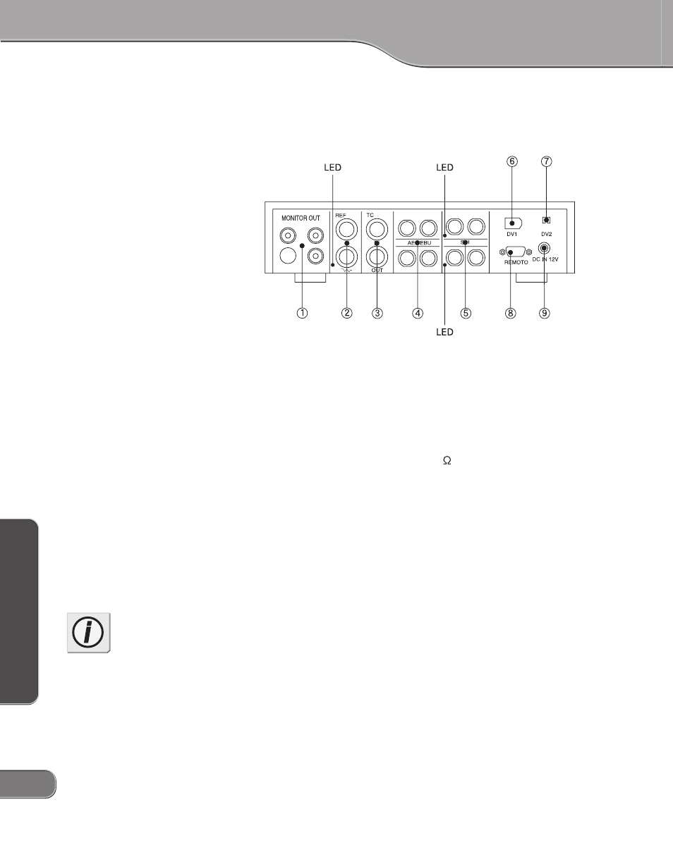
ADVC-1000 Rear Panel
The rear panel of the ADVC-1000 contains the following connectors
1. MONITOR OUT --------- Output connectors for video monitor,
speakers.
2. REF ------------------------- Input connectors receiving sync signal.
The LED lights red when sync signal
input is detected. The REF connector
has through output. If a cable is not
connected to the output connector, it
has a 75 automatic termination.
3. TC --------------------------- Time code I/O connectors.
4. AES/EBU ------------------ Digital audio signal I/O connectors.
5. SDI -------------------------- I/O connectors for digital video and
embedded audio signals. When SDI input
is detected, the LED next to the SDI input
connector lights red. During SDI output,
the LED next to the SDI output connector
lights red.
6. DV1 ------------------------- 6-pin DV connector.
7. DV2 ------------------------- 4-pin DV connector.
8. REMOTE ------------------ Remote control connector.
9. DC-IN 12V ---------------- 12V DC power supply terminal. Use the
AC adapter provided.
Info
When connecting a PC to the
ADVC-1000 unit, make sure that
the PC’s power is turned off.