3 amx-1101-drp / amx-1101-drp-3ru rear panel – Grass Valley AMX-1101 User Manual
Page 7
GUIDE TO INSTALLATION AND OPERATION
AMX-1101 | 3
2.3
AMX-1101-DRP / AMX-1101-DRP-3RU Rear Panel
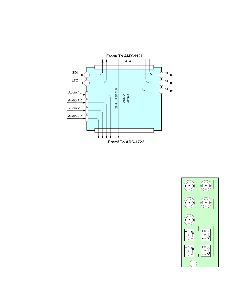
The following diagram shows the signal flow through the AMX-1101-DRP / AMX-1101-DRP-3RU rear panel.
Figure 1.1 Signal flow in the AMX-1101-DRP rear panel
The rear panel connections are as follows:
SDI IN – serial digital video input
Connect a serial digital video signal, conforming to the SMPTE 259M standard, to the BNC
labeled SDI IN.
LTC IN
Connect a time code signal (LTC, conforming to SMPTE 12M), for embedding into the output
SDI signal.
ANALOG AUDIO IN (2 stereo pairs)
Connect an analog audio signal, which will be digitized in the ADC-1722 and then embedded
into the SDI video in the AMX-1121.
SDI OUT – serial digital video outputs (3)
These three connectors carry the output SDI signal, consisting of the input SDI signal into
which audio and LTC have been embedded
SDI OUT
+ G –
+ G –
+ G –
+ G –
ANALOG AUDIO IN
1 LEFT
1 RIGHT
2 LEFT
2 RIGHT
LTC IN
SDI IN
SDI OUT
2
1
3
AMX-1101