Connecting microphones to the prm – Grass Valley 3e Student CameraMan User Manual
Page 16
Chapter 2
10 CameraMan 1-CCD and 3-CCD Student Camera System Installation and Operations
The PRM Power Supply and CameraMan Power
Supply should not be interchanged.
Connecting Microphones
to the PRM
1.
Place the microphones around the room, and
label them accordingly (i.e.: numbered 1, 2, 3,
etc.)
2.
Connect the microphone via the appropriate
length microphone extension cable (not
included) to the optional microphone “Y” Cable
(5-pin mini XLR to 3-pin male XLR/2-pin female
Phoenix connector).
3.
Connect 3-pin male XLR to your room’s micro-
phone mixer/phantom power source.
4.
Connect the 2-pin female Phoenix Connector
(green connector block) to the appropriately
labeled PRM input (i.e.: 1, 2, 3, etc).
5.
Repeat steps 2-4 for all remaining microphones.
If you are using non-Grass Valley supplied “Y”
Cables, follow these instructions to connect the 2-
pin female Phoenix Connector wires to the green
connector block:
1.
Strip a short section (approximately 0.15”) off the
end of the wire.
2.
Insert the wire into the screw terminal slot on the
connector plug.
3.
Tighten the terminal screw.
4.
Repeat steps 1-3 for the other 4 wire-pairs in that
connector block.
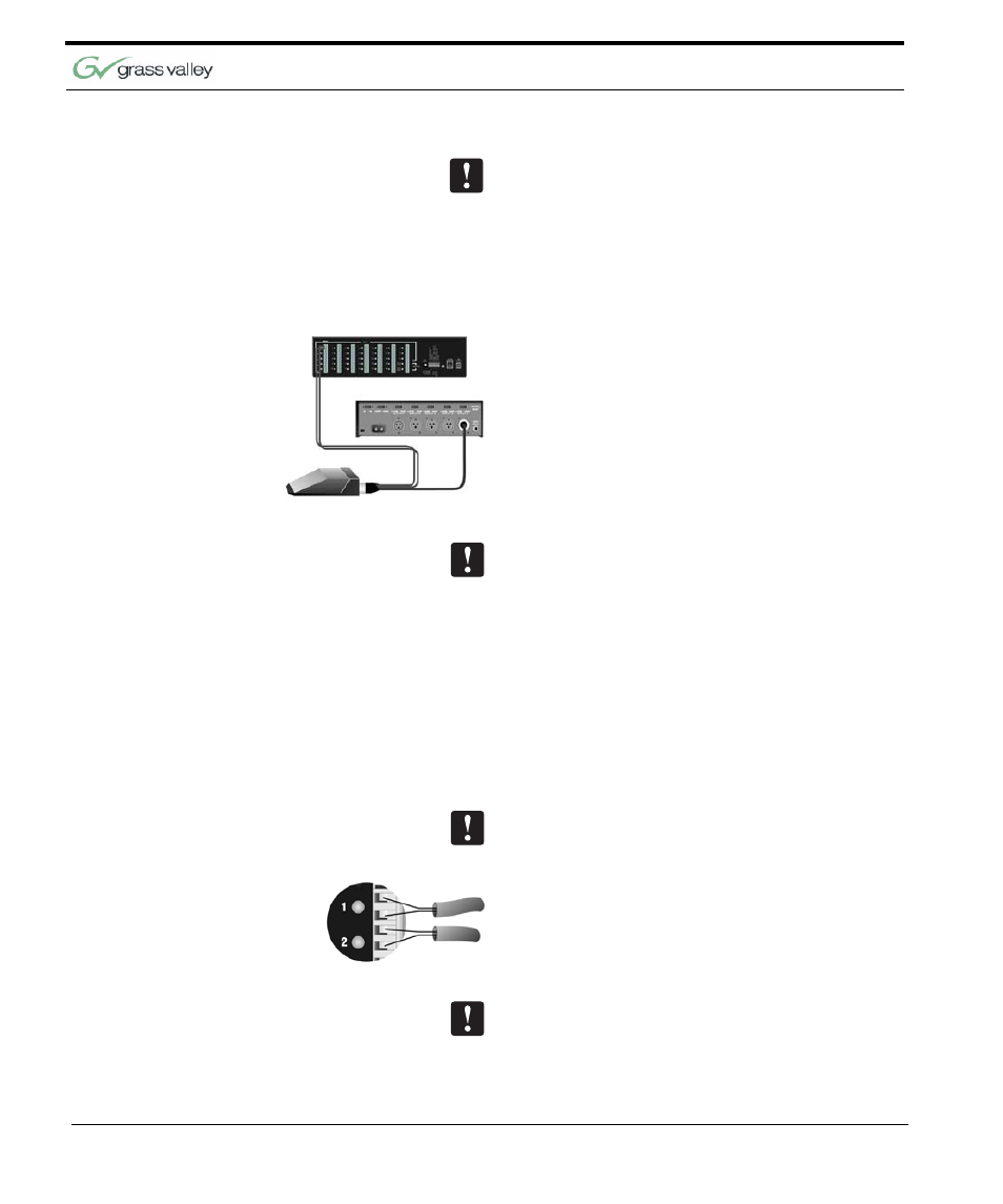
If you are using microphones which are polarity sen-
sitive, the inputs should be wired as follows:
1.
The positive lead, from the contact closure of the
microphone, should be wired to the top input of
the pair, labeled “+”.
2.
The negative lead, from the contact closure of
the microphone, should be wired to the lower
input of the pair, labeled “-”.
All of the inputs labeled “-” are wired together inter-
nally and connected to ground.