Icontrol interface, Status tab, Config tab – Grass Valley DDA-1113 User Manual
Page 11
GUIDE TO INSTALLATION AND OPERATION
DDA-1113 | 11
3.3 iControl Interface
The operation of the DDA-
1113 may be controlled using Miranda’s iControl system.
This section describes the control panels associated with the DDA-1113 and their
uses.
P
lease consult the iControl User’s Guide for information about setting up and
operating iControl.
In iControl Navigator or iControl Websites, double-click on the DDA-1113 icon to
open the control panel.
Status Icons
At the top, to the left of the Miranda logo, are two status icons that report various
aspects of the card’s operation.
The leftmost (CTRL) icon shows whether card configuration is manual [LOC] or via
iControl [REM]. The second icon reports the input status.
Move the cursor over an icon to see its current status in the message area below
the icons. If there is an error status, the message will appear automatically. If there
are multiple error messages, the display will cycle through them.
Load Factory
The Factory profile is a read-only set of factory-selected values that can be used to
return your DDA-1113 to a standard operating condition.
The default values are shown as underlined in the DDA-1113 Menu on page 10.
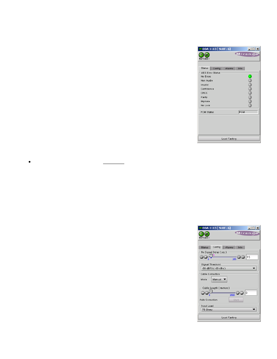
3.3.1 Status Tab
This tab displays the status of the various errors that could be associated with the input signal.
The PCM Status box will display either PCM, non-audio, Dolby-E or AC-3 according to the type of audio signal.
3.3.2 Config Tab
No Signal Delay
This tab sets the card’s behavior in the event of a loss or absence of audio signal
content.
A signal absence is declared when the signal level is lower than the signal threshold
during the selected period.
The threshold can be set through the pull-down box to
–72, -66, -60, -54 or -48
dBFS, the default value is
–60 dBFS.
The signal absence period can be adjusted from 0 to 255 seconds. The default
value is set to 15 s, an input box is available to enter a numerical value directly.
Cable Correction
Mode MANUAL
This mode allows a manual adjustment of the correction applied to the input signal.
Look at the input status icon to facilitate the setting. An input box is available to
enter a numerical value directly.
Figure 3.3 Config Tab
Figure 3.2 Status Tab