Grass Valley FIO-1901-TT User Manual
Page 16
GUIDE TO INSTALLATION AND OPERATION
12 | FIO-1901-TT
Section 2. The left portion of the window contains access buttons for all the parameter groups, which become
highlighted when they are selected; the main panel (3) then displays the group’s set of parameters. Each of the
groups is described in detail below.
Section 3. The main panel contains all the parameters specific to the group selected.
Each of the panels associated with the groups accessed from the buttons in Section 2, and shown in Section 3, is
described individually in the following sections.
3.3.2 The
Status panel
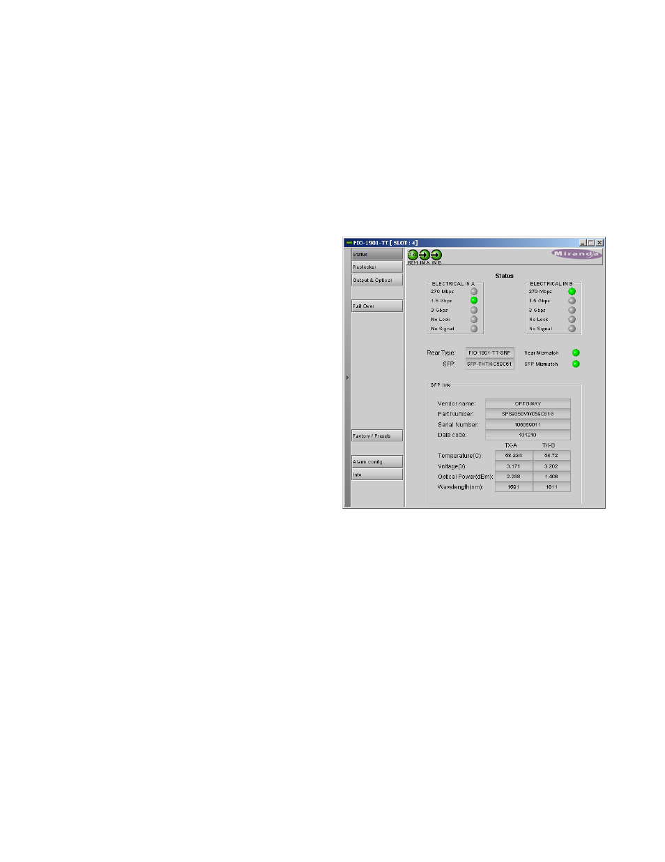
This panel reports the status of this FIO-1901-TT card, its
rear panel, its SFP module, and the signals arriving at the
electrical inputs on the rear panel.
ELECTRICAL IN A and ELECTRICAL IN B
• Shows the incoming data rate when a signal is
successfully received (green icons)
• Identifies No Signal or No Lock conditions (red icons)
Rear Type – the data box identifies the rear panel installed
in the Densité frame for this FIO-1901-TT.
Rear mismatch – the icon is green when a compatible rear
panel is installed and red when an incompatible rear panel is
installed.
SFP - the data box identifies the SFP module installed in the
rear panel for this FIO-1901-TT.
SFP mismatch – the icon is green when a compatible SFP
module is installed and red when an incompatible SFP
module is installed.
SFP Info – the data boxes in this section give information
about the SFP module itself, and measured data about the operating status of the two transmitters TX-A and TX-B
Figure 3.4 Status panel