Grass Valley Kalypso Installation Planning Guide User Manual
Page 84
Advertising
84
Kalypso Installation Planning Guide
Section 4 — Kalypso HD Frame
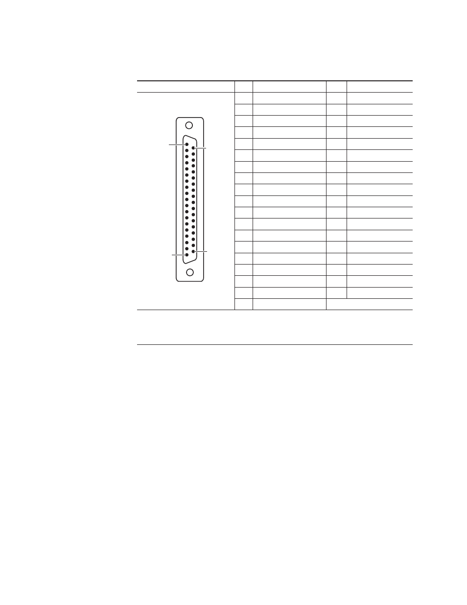
Table 27. GPI Inputs
GPI Inputs Port
Pin
Function
Pin
Function
1
Chassis Ground
20
IN 1 B
2
IN 1 A
21
IN 2 B
3
IN 2 A
22
IN 3 B
4
IN 3 A
23
IN 4 B
5
IN 4 A
24
Chassis Ground
6
IN 5 A
25
IN 5 B
7
IN 6 A
26
IN 6 B
8
IN 7 A
27
IN 7 B
9
IN 8 A
28
IN 8 B
10
Chassis Ground
29
IN 9 B
11
IN 9 A
30
IN 10 B
12
IN 10 A
31
IN 11 B
13
IN 11 A
32
IN 12 B
14
IN 12 A
33
Chassis Ground
15
IN 13 A
34
IN 13 B
16
IN 14 A
35
IN 14 B
17
IN 15 A
36
IN 15 B
18
IN 16 A
37
IN 16 B
19
Chassis Ground
Notes:
Inputs are opto-isolated.
A and B are polarity independent.
Apply from 5 to 24 volts to A and B to turn on.
Pin 1
Pin 19
Pin 20
Pin 37
D-37 Female
Advertising