Operation indicator leds – Grass Valley KAM-DEC-2AES v.4.0.3 User Manual
Page 14
14
KAM-DEC-2AES Instruction Manual
Power Up
Operation Indicator LEDs
provides a complete list of possible operating conditions and the
resulting indicator status.
A red FAULT LED indicates an error situation.
output and LED indications for the various input/reference combinations
and user settings.
Note
The yellow
COMM
and
CONF
LEDs are used for the module location function
that is enabled using the 2000NET GUI. The module location function causes
these LEDs to repeatedly flash concurrently three times followed by an off
state of 900 ms duration (see
).
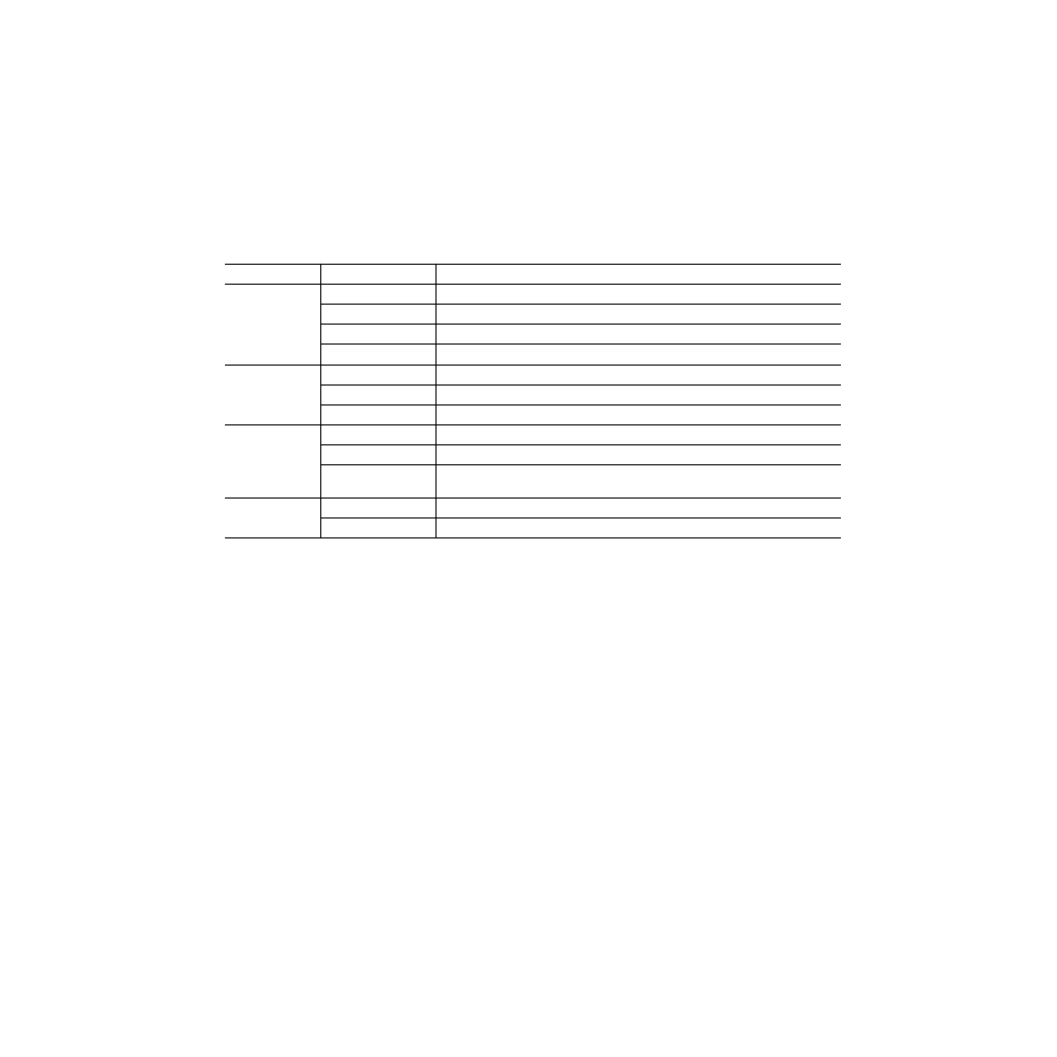
Table 2. Indicator LEDs and Conditions Indicated
LED
Indication
Condition
Fault
(red)
Off
Normal operation
On continuously
Module has detected internal fault
Long flash
One of the inputs is missing or is wrong standard
Short flash
Errors present in SDI and/or AES/EBU input
COMM
(yellow)
Off
No activity on frame communication bus
Three flash/off pattern
Module Location command received from a remote control system
Short flash
Activity present on the frame communication bus
CONF
(yellow)
Off
Module is in normal operating mode
Three flash/off pattern
Module Location command received from a remote control system
On continuously
Module is initializing, changing operating modes or updating firmware. (When solid on along
with Fault LED on, board has failed to load data.)
PWR
(green)
Off
No power to module or module’s DC/DC converter failed
On continuously
Normal operation, module is powered