Status boxes, Information, Status web page – Grass Valley Kameleon HD Multi-Function Modules v.3.2.0 User Manual
Page 38
38
KAM-HD-MULTI—Instruction Manual
Kameleon HD Links and Web Pages
Status Web Page
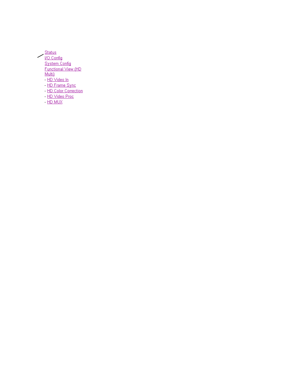
Use
this
link
The Status web page provides an overall indication of the health of the
system, audio configuration information, rear module type installed, and
provides links to web pages for the active components:
•
Status Header – see
Status and Identification Header on page 35
•
Color-coded communication status for each component and path,
•
Summary of all fault/warning conditions, and
•
Textual module status, front module, and rear module properties.
Status web page views differ according to the different audio configura-
tions. The different audio configurations are shown in the following illus-
trations:
•
8 In/0 Out
– the Status web page for a module with an audio configura-
tion of 8 inputs and no outputs is illustrated in
Refer to this illustration for an example of a full Status web page.
•
4 In/4 Out
– the reporting section of a Status web page for a module with
an audio configuration of 4 inputs and 4 outputs is illustrated in
.
•
0 In/ 8 Out
– the reporting section of a Status web page for a module with
an audio configuration of no inputs and 8 outputs is illustrated in
(Bal-
anced Rear).
Status Boxes
Each box represents a Kameleon front or rear module. The
KAM-HD-MULTI-UR or -BR link in the Rear I/O Module box will take you
to the I/O Config web page for setting input and output names. The
module link in the Front Processing module box will take you to the Func-
tional view web page containing the configuration links.
The arrows represent audio and video signal paths that may or may not be
monitored. Audio paths represent AES audio inputs. These elements act as
links when their function is active (indicated by underlined function
name).
Color code:
•
Green = Pass – operating as expected.
•
Yellow = Warning – signal is absent, has errors, or is misconfigured.
•
Red = Fault – a component has failed.
•
Gray = Not monitored.