Gpi in, tally, gpi out – Grass Valley K-Frame Installation Planning Guide User Manual
Page 53
K-FRAME — Installation Planning Guide
53
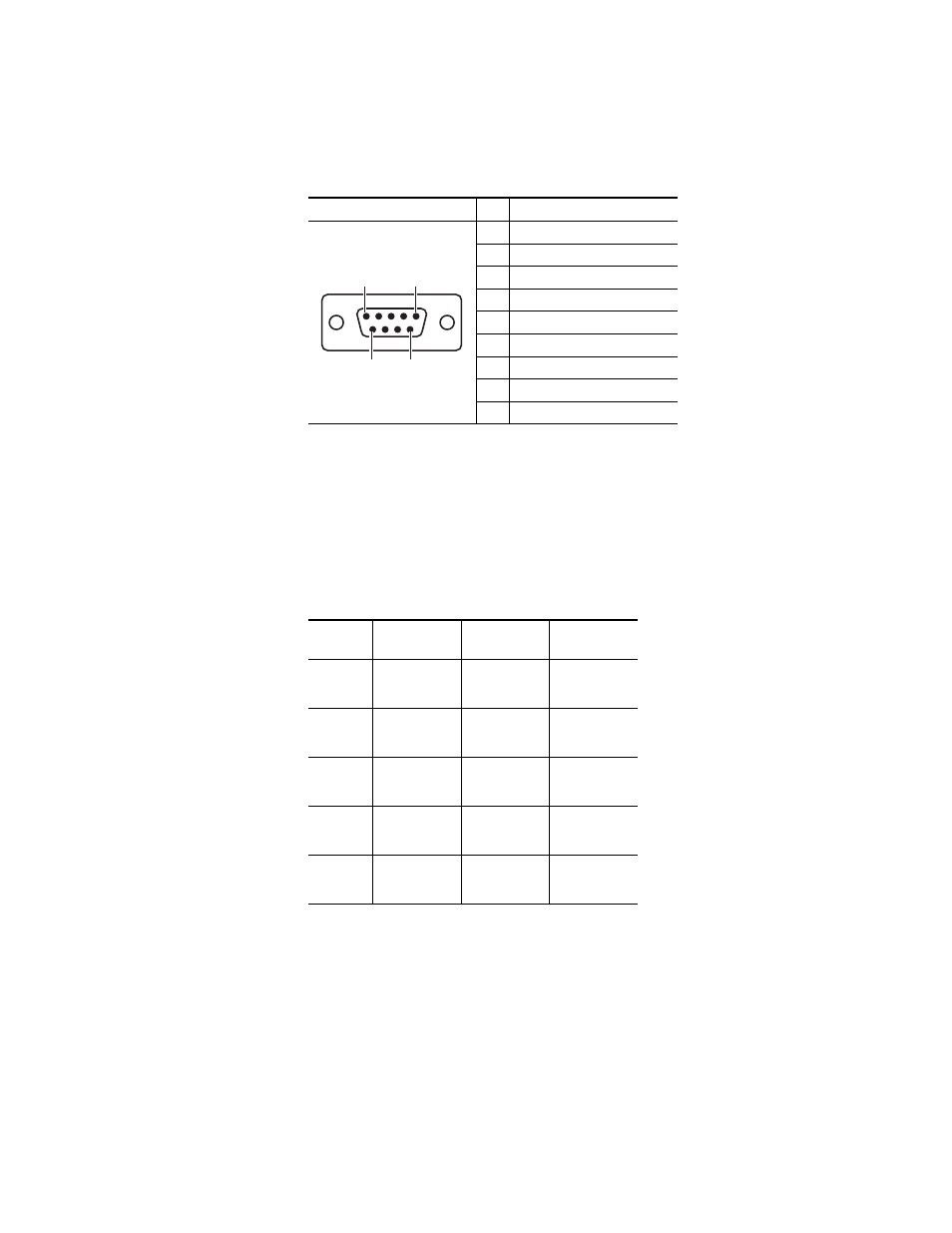
Pin Assignments
Standard VGA and keyboard ports, present on all processor boards, are
also available for maintenance.
GPI In, Tally, GPI Out
Each Input Module has a 50 pin connector for GPI and Tally. The connectors
are arranged in left to right order on the rear of the Standard (13-RU)
K-Frame, and in top to bottom order on the Compact (6RU) K-Frame.
Table 6. RS-232 Pinouts
Socket
Pin
Signal
1
Chassis Ground
2
Transmit Data
3
Receive Data
4
Not used
5
Signal Ground
6
Not used
7
Clear to Send
8
Request to Send
9
Not used
Table 7. Input Module Connectors
Module
Number
Signals
6RU Frame
13 RU Frame
1
GPI In 1-8
Tally 1-24
GPI Out 1-8
Yes
Yes
2
GPI In 9-16
Tally 25-48
GPI Out 9-16
Yes
Yes
3
GPI In 17-24
Tally 49-72
GPI Out 17-24
No
Yes
4
GPI In 25-32
Tally 73-96
GPI Out 25 - 32
No
Yes
5
GPI In 33-40
Tally 97-120
GPI Out 33-40
No
Yes
Pin 1
Pin 5
Pin 6
Pin 9
D-9 Female