Control surface cabling, Overview, Section 5 — control surface cabling – Grass Valley Kayenne K-Frame Installation Planning Guide Dec 03 2014 User Manual
Page 43: Kayenne k-frame — installation planning guide 43
KAYENNE K-FRAME — Installation Planning Guide
43
Section
5
Control Surface Cabling
Overview
Note
This section covers. Kayenne control surface cabling. Refer to the separate
K-Frame documentation set for K-Frame system, and Video Processor Frame
cabling information.
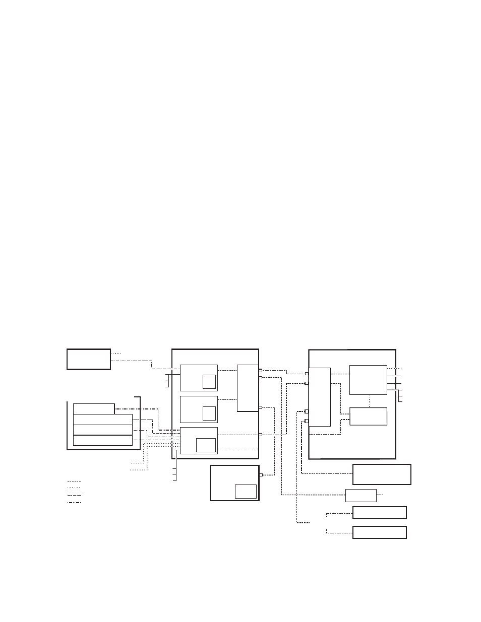
The K-Frame system uses Ethernet, serial, and USB connections. Custom
multi-pin cabling is also used to connect the Kayenne Panel Control Unit
(PCU) to Kayenne control surface and Menu Panel components. The
K-Frame Video Processor and PCU each have built-in Ethernet switches.
Tally outputs and GPI I/O (General Purpose Interface Input/Output)
control is also available (
).
Figure 1. Kayenne K-Frame System Communications Overview
8877_02
Technical
Director’s
Laptop
CD-ROM
Drive
Disable Internet or
Wireless Connections
Isolate K-Frame System
from External Network
Ethernet
Serial Control
Custom Multi-Pin (Menu, 15m / 50ft max length)
Custom Multi-Pin (Panel, 15m / 50ft max length)
Maintenance Only (board front edge)
*
Panel Main LAN
Panel Aux LAN
(not used)
Eh
te
rne
t Swi
tch
1
2
3
4
5
6
7
8
Kayenne PCU
Menu
CPU
Hard
Disk
Menu
CPU
(option)
Hard
Disk
Panel
CPU
Compact
Flash
Menu Panel
Kayenne Control Panel
Remote Aux Panel
Local Aux Stripe
ME Stripe
ME Stripe
ME Stripe
(Up to 8 Stripe Connections)
USB
RS-422/485
Facility LAN
Switch
Ethernet
Router
Remote Aux Panel
Clip Store
(Image Store Clips)
Internal Control
K-Frame Video Processor
Video
Processor
CPU
Image Store
Eh
te
rne
t Swi
tch
7
8
1
2
3
4
5
6
USB (4)*
Keyboard, VGA*
RS-232*
RS-422/485 (8)
GPI In/Out
Tally
Keyboard, VGA*
RS-232*
USB (2)*
USB (4)
RS-232*
USB (2)*
Keyboard, VGA*