3 operation, 1 powering up, 2 front panel indicators and controls – Grass Valley KXI-DVI-Bridge User Manual
Page 12: Powering up, Front panel indicators and controls
USER’S MANUAL
3 Operation
The KXI-DVI-Bridge has no local controls beyond the power switch and the reset pushbutton. The behavior
of the unit depends on the input DVI signal(s) and its operating mode. The operating mode is determined
ONLY at power-up by the presence or absence of the dongle in the RS-232/GPI port on its rear panel. At
power-up, the KXI-DVI-Bridge runs an internal check for the presence of this dongle. If the dongle is not
present, the device will only operate as a Kaleido input device (Mode A). If it is present, the unit operates will
operate as either a Kaleido input or output device (Mode B). Refer to page 2 for a description of these
operational modes.
3.1 Powering
Up
The power switch is located on the rear panel of the KXI-DVI-Bridge, just above the power connector.
Connect the provided power supply to the power connector and set the switch to ON (I). Make sure the
dongle is properly connected if you want to enable output conversion.
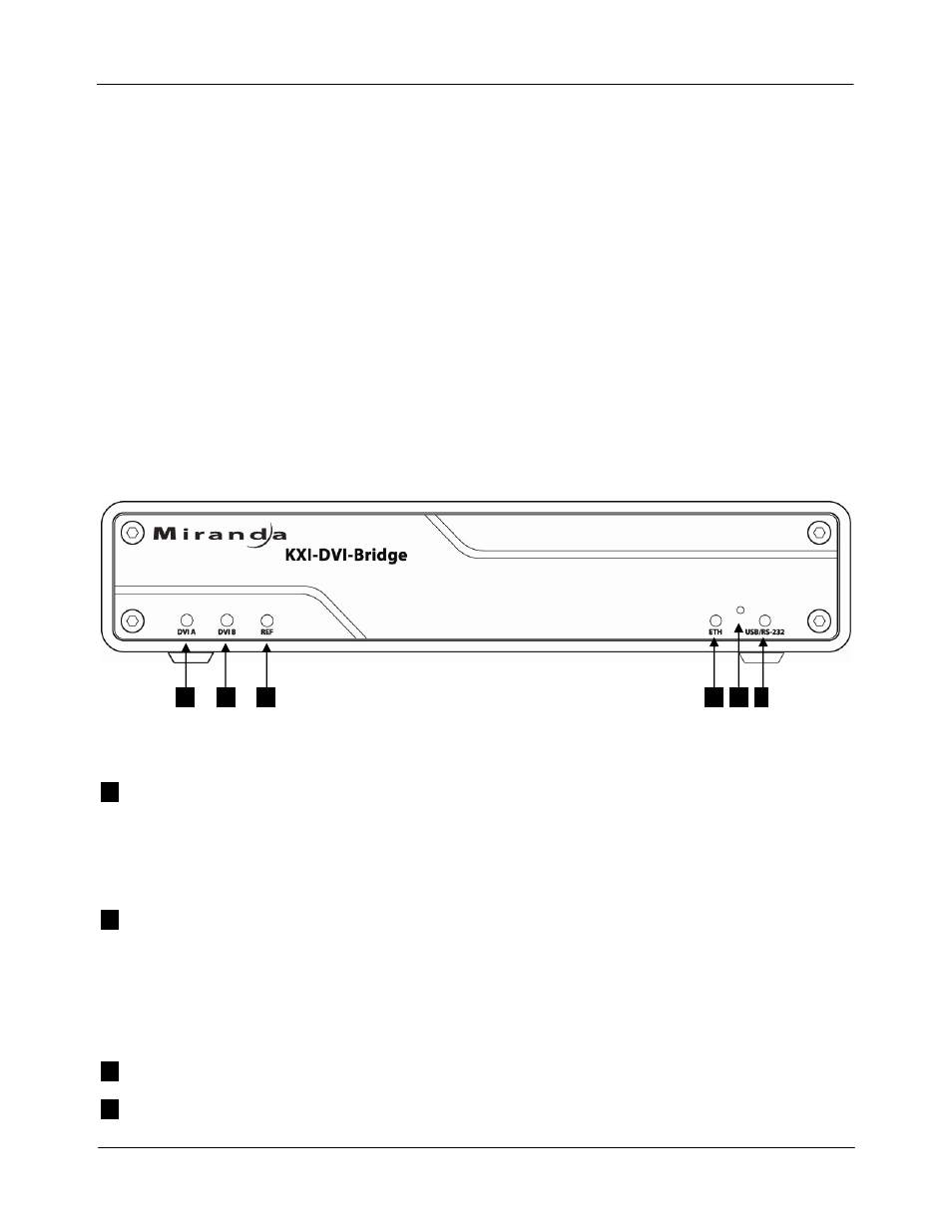
3.2 Front Panel Indicators and Controls
There are five Input Status LEDs which are mounted on the front edge of the KXI-DVI-Bridge’s circuit board,
and which can be seen through holes in the front panel of the case.
1
2
3
4
5
6
Status LEDs
1
DVI A
GREEN when a valid input is detected on DVI-D IN A
RED when no valid input is detected on DVI-D IN A
AMBER when a valid DVI signal is detected but not 60Hz on DVI-D IN A (only for input
device mode)
2
DVI B
When the DVI input mode is DUAL-HEAD mode (software configuration):
GREEN when a valid input is detected on DVI-D IN B
RED when no valid input is detected on DVI-D IN B
AMBER when a valid DVI signal is detected but not 60Hz on DVI-D IN B (only for input
device mode)
3
REF
OFF – no reference – not used
4
ETH
OFF – no link – not used
8 | KXI-DVI-Bridge