Grass Valley M-222D Aug 02 2004 User Manual
M-series ivdr quick start guide, Analog audio analog audio, For models with digital audio
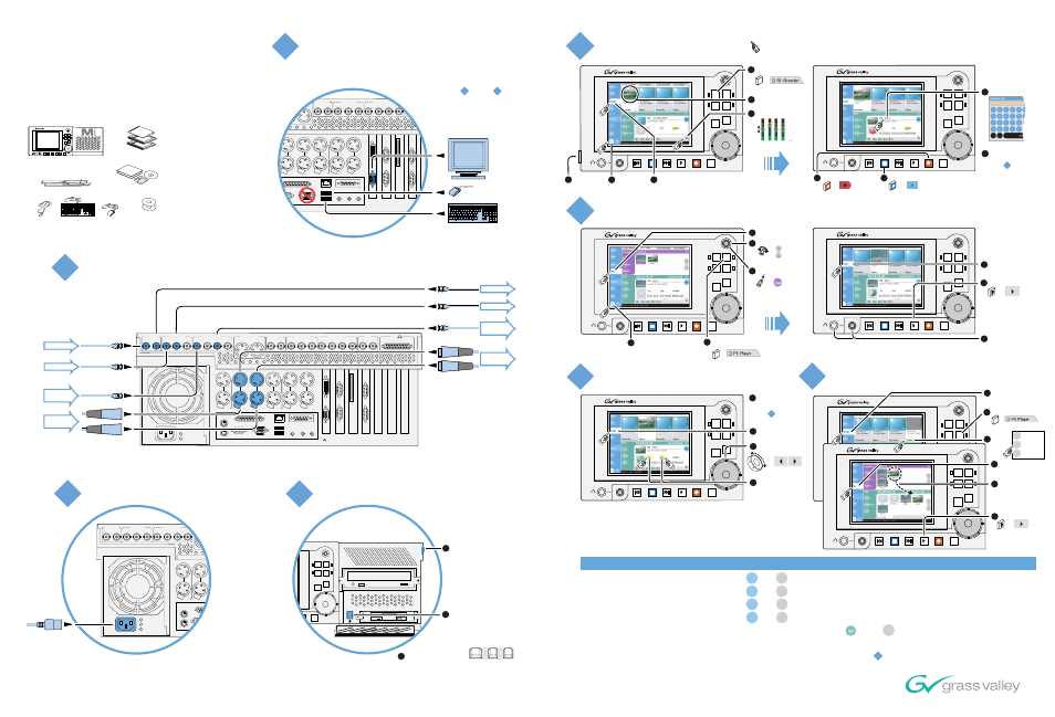
For systems with no front panel,
connect keyboard, mouse, and
monitor
M-Series iVDR
Quick Start Guide
For models with digital audio
Before you begin, unpack and identify the following items:
M-Series iVDR
(Optional front panel shown)
VAR
JOG
SHTL
R1
P2
P1
R2
Pro
fi
le
X
Pro
fi
le
X
Pro
fi
le
X
Pro
fi
le
X
Pro
fi
le
X
Gra
ss V
al
ley
Gro
up
Pro
fi
le
X
Pro
fi
le
X
Pro
fi
le
X
Pro
fi
le
X
Pro
fi
le
X
Gra
ss V
al
ley
Gro
up
Aqu
sdg
sgd
s
Aqu
sdg
sgd
s
Aqu
sdg
sgd
s
Aqu
sdg
sgd
s
Aqu
sdg
sgd
s
Aqu
sdg
sgd
s
Gra
ss
Va
lle
y G
rou
p
Gra
ss
Va
lle
y G
rou
p
Gra
ss
Va
lle
y G
rou
p
Gra
ss
Va
lle
y G
rou
p
Keyboard
Power Cord
Mouse
System Software CD
Release Notes
User Manual
Service Manual
Licenses and
Warranties
Rack slides
P1 CH1
R2 CH1
P2 CH2
OUT
IN
P1 LTC
P1 CH2
P2 LTC
P2 CH1
R1 LTC
R2 CH2
R2 LTC
R1 CH2
R1 CH1
Analog
Audio
Analog
Audio
Pus
h
Pus
h
Pus
h
Pus
h
Pus
h
Pus
h
R1 IN
R1 IN
CH 1/2
CH 1/2
CH 3/4
CH 3/4
P1 OUT
P1 OUT 1
L
R
P1 OUT 2
R2 IN
R2 IN
CH 1/2
CH 1/2
CH 3/4
CH 3/4
P2 OUT
P2 OUT 1 P2 OUT 2
CMPST R1 & P1
SDI R1 & P1
AES/EBU R1 & P1
CMPST R2 & P2
SDI R2 & P2
AES/EBU R2 & P2
REF
COMPOSITE LOOP
THRU
R2 IN
P2 OUT
R1 IN
P1 OUT
AUD MON OUT
GPI
!
PORT 3
PORT 4
RS422
PORT 1
PORT 2
RS422
SCSI
VGA
FRONT
PANEL
Video
Audio
Digital
Ch 1 & 2
Analog
Ch 1 & 2
SDI
AND/OR
Composite
Recorder 1 (R1) Input
Player 1 (P1) Output
Audio
Video
Composite
SDI
OR
OR
Digital
Ch 1 & 2
Analog
Ch 1 & 2
AND/OR
Recovery Program CD
P1 CH1
R2 CH1
P2 CH2
OUT
IN
P1 LTC
P1 CH2
P2 LTC
P2 CH1
R1 LTC
R2 CH2
R2 LTC
R1 CH2
R1 CH1
Analog
Audio
Analog
Audio
Pus
h
Pus
h
Pus
h
Pus
h
Pus
h
Pus
h
R1 IN
R1 IN
CH 1/2
CH 1/2
CH 3/4
CH 3/4
P1 OUT
P1 OUT 1
L
R
P1 OUT 2
R2 IN
R2 IN
CH 1/2
CH 1/2
CH 3/4
CH 3/4
P2 OUT
P2 OUT 1 P2 OUT 2
CMPST R1 & P1
SDI R1 & P1
AES/EBU R1 & P1
CMPST R2 & P2
SDI R2 & P2
AES/EBU R2 & P2
REF
COMPOSITE LOOP
THRU
R2 IN
P2 OUT
R1 IN
P1 OUT
AUD MON OUT
GPI
!
Connect input and output
P1 CH1
R2 CH1
P2 CH2
OUT
IN
P1 LTC
P1 CH2
P2 LTC
P2 CH1
R1 LTC
R2 CH2
R2 LTC
R1 CH2
R1 CH1
Analog
Audio
Analog
Audio
Pus
h
Pus
h
Pus
h
Pus
h
Pus
h
Pus
h
R1 IN
R1 IN
CH 1/2
CH 1/2
CH 3/4
CH 3/4
P1 OUT
P1 OUT 1
L
R
P1 OUT 2
R2 IN
R2 IN
CH 1/2
CH 1/2
CH 3/4
CH 3/4
P2 OUT
P2 OUT 1 P2 OUT 2
CMPST R1 & P1
SDI R1 & P1
AES/EBU R1 & P1
CMPST R2 & P2
SDI R2 & P2
AES/EBU R2 & P2
REF
COMPOSITE LOOP
THRU
R2 IN
P2 OUT
R1 IN
P1 OUT
AUD MON OUT
GPI
!
Connect power cable
VAR
JOG
SHTL
R1
P2
P1
R2
Switch power on
Unlatch and
lower front door
Push the standby switch and wait
for system startup. M-Series
iVDR control applications start
automatically.
Note: Other inputs and outputs
connect similarly. Read the M-Series
User Manual for complete connection
instructions.
1
2
If you have a problem with... Make corrections here...
Copyright © 2004 Thomson Broadcast and Media Solutions, Inc.
071-8326-00 June 3, 2004
Play a clip
*Note: Controls marked with
an asterisk (*) are provided
on the VGA monitor only.
Record a clip
Trim a clip
Create a playlist
If your system has no front panel you must
accomplish steps through using
keyboard, mouse, and monitor rather than
using the front panel as illustrated.
2
1
3
4
6
5
7
8
5
8
VAR
JOG
SHTL
R1
P2
P1
R2
VAR
JOG
SHTL
R1
P2
P1
R2
P1
Display split-screen view
Select play
channel 1
Select
Monitor
Monitor audio
with headphones
Play the clip
Select
Clips
Choose a clip
Load the clip
6
7
8
2
3
Select
Clips
4
4
5
1
or
or
or
or
*
VAR
JOG
SHTL
R1
P2
P1
R2
Press latch
and adjust
viewing angle
1
VAR
JOG
SHTL
R1
P2
P1
R2
3
Select
Monitor
Display
split-screen
view
2
Verify video source
5
6
Adjust audio
7
Start record
8
Stop record
9
Rename clip
10
R1
Select record
channel 1
4
or
or
or
*
*
VAR
JOG
SHTL
R1
P2
P1
R2
Select channel P2
2
or
P2
VAR
JOG
SHTL
R1
P2
P1
R2
Select
Monitor
Locate a frame
2
3
Set in or out
mark to current
timecode
4
or
*
Load a clip into
play channel 1
as explained in
step
1
6
VAR
JOG
SHTL
R1
P2
P1
R2
Select
Monitor
Play the list
1
Select
Playlist
on P2
3
5
Drag clips to list
Aqu
sdg
sgd
s
Aqu
sdg
sgd
s
Aqu
sdg
sgd
s
Aqu
sdg
sgd
s
Aqu
sdg
sgd
s
Aqu
sdg
sgd
s
Gra
ss
Va
lle
y G
rou
p
Gra
ss
Va
lle
y G
rou
p
Gra
ss
Va
lle
y G
rou
p
Gra
ss
Va
lle
y G
rou
p
Aqu
sdg
sgd
s
Aqu
sdg
sgd
s
Aqu
sdg
sgd
s
Aqu
sdg
sgd
s
Aqu
sdg
sgd
s
Aqu
sdg
sgd
s
Gra
ss
Va
lle
y G
rou
p
Gra
ss
Va
lle
y G
rou
p
Gra
ss
Va
lle
y G
rou
p
Gra
ss
Va
lle
y G
rou
p
6
or
*
Playlist
Player
Remote AMP
Load and play the
clip as shown in
step
6
(Rotate)
(Push)
Video standard (NTSC/PAL)
System | Configuration | System
Video input source (SDI/Composite)
System | Configuration | Channel | R1 | Video Input
Recording timecode
Audio output (Embedded Audio Group)
System | Configuration | Channel | P1 | Audio Output
On the Recorder context menu choose Options | Timecode
Audio input source (Analog, Digital, Embedded)
System | Configuration | Channel | R1 | Audio Input
Playing a clip
Verify that the clip is loaded in a play channel rather than a record channel
Verify the monitor connection as in step
The VGA monitor
For other problems refer to the M-Series Service Manual.
1
Use the touch-screen on the front panel.
If no front panel, press
after startup to set correct VGA display
settings. To modify VGA display settings,
see the M-Series User Manual.
Ctrl
+
+
Alt
C
3