Nv9700, Cabling, Making it work – Grass Valley NV9700 v.1.3 User Manual
Page 4
4
Rev 1.3 • 25 Nov 14
NV9700
Connections
Cabling
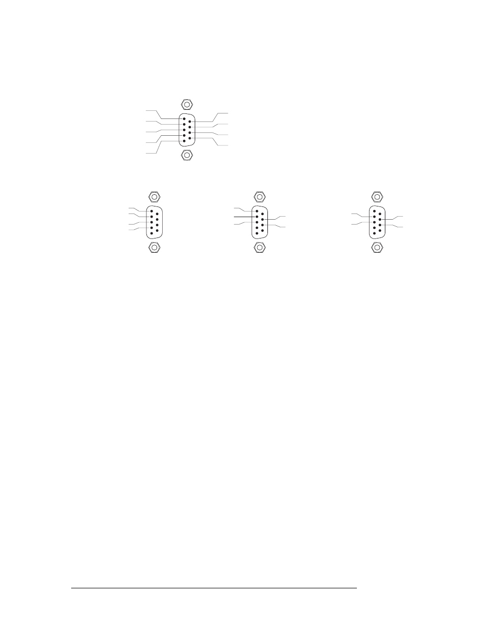
This is the pinout for each of the NV9700’s controller ports:
Depending on the serial card installed in your NV9000 controller, the DE9 ports to which you will
connect the NV9700 will have any of 3 pinouts:
Your cabling must accommodate the pinout. In all cases, Tx– connects to Rx– and Tx+ to Rx+.
(The NV9700’s ports are female. The serial card’s breakout ports might be either male or female.)
Making It Work
To make the NV9000 communicate with the NV9700 you must add the following registry entry:
\HKLM\SOFTWARE\NVISION/CTRLSYS/CONFIG/SerialMonitor0
The entry is a
REG_DWORD
and its value is that of COM port you are using for the NV9700. For
instance, the value is
0x0000006
for COM port 6.
Repeat this on the secondary system controller too if your NV9000 system is redundant.
Important: restart NVAGENT so it can detect the registry change.
In the general case, the registry entry is:
SerialMonitorN
where N is an integer starting at 0 and continuing contiguously until all the intended serial ports are
listed. When these keys are nonzero, the system controller listens for status and monitoring queries
on the port.
1
5
9
6
Gnd
Tx
Rx +
Gnd
n.c.
Gnd
Tx +
Rx
Gnd
1
5
9
6
Rx
Tx
Tx +
Rx +
(RocketPort) Non-SMPTE
1
5
9
6
Tx +
Rx +
Rx
Tx
Moxa CP-118U and
other Moxa breakout
cables
1
5
9
6
Rx
Tx +
Tx
Gnd
Rx +
Grass Valley WC0153 cable
end for Moxa NPort 6650