Making signal connections, Installation – Grass Valley NV5128 v.2.5 User Manual
Page 60
50
Rev 2.5 • 24 Sep 09
3. Installation
Making Signal Connections
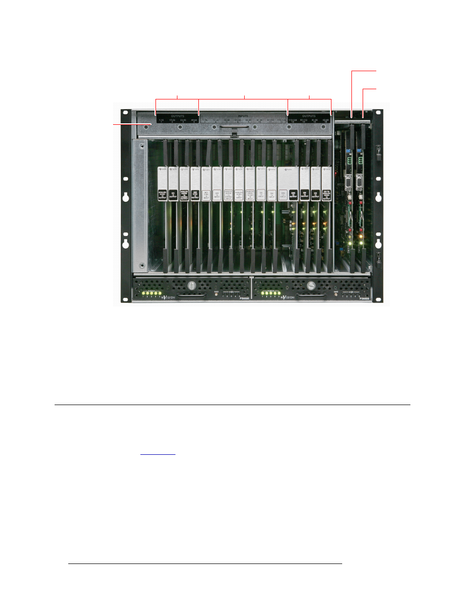
Figure 3-7. Card Locations (Front View)
4 Press each lever downward so that the lever is tucked into the channel at the edge of the shelf on
the top and bottom. When the door is closed, pressure from the door ensures that the card is
fully seated with the motherboard.
5 Reinstall and close the frame front door after all cards have been installed. The door must be
closed for the router cooling system to work properly.
Making Signal Connections
For the NV5128 to route incoming and outgoing signals properly, the I/O connections housed on
backplanes on the rear of the router must be connected to cables that receive and distribute the sig-
nals. (See
on page 13.) The NV5128 contains a maximum of 128 input connections and
a maximum of 128 output connections. The total number of connections depends on the type of sig-
nals being routed and the corresponding backplane installed.
Figure 3-8 shows the rear of the router with backplanes containing connectors for receiving and
distributing signals and the location of inputs and outputs for signal connections.
Slots 1–4
(Outputs 1–64)
Slots 5–12
(Inputs 1–128)
Slots 13–16
(Outputs 128–65)
Secondary
Control
Primary
Control
Fan Tray
Main Power Supply (PS6000)
Redundant Power Supply (PS6000)