Misc. topics – Grass Valley NV8900 Series v.1.3 User Manual
Page 22
14
Misc. Topics
Installation
Although the switch is not used at present, in the future MRC will use the switch position to
distinguish multiple NV8900s on an Ethernet LAN.
Use a small screwdriver to turn the rotary switch.
In a network, all devices must have unique IP addresses. An IP address is determined (at
least initially) by the rotary switch at the front of the MADI interface. The rotary switches
must (at least initially) be distinct.
2 Mount, and secure, the MADI interface in the rack.
For the 1RU interfaces, the mounting holes are spaced 1.25
″ (31mm) vertically and allow
approximately 1/8
″ (3mm) of movement horizontally.
For the 2RU interfaces, the 3 mounting holes on each side are spaced 1.25
″ (31mm) and
1.75
″ (44mm) (3″, 76mm, overall) vertically and allow approximately 1/8″ (3mm) of play hor-
izontally.
You might not have enough space to reach behind the MADI interface and make
connections. In that case, leave this step until last.
3 If you are using the MADI interface on a network (for MRC), connect an Ethernet cable (RJ-
45) from the network switch to the Ethernet port of the MADI interface. Also connect an
Ethernet cable from your PC running MRC to the Ethernet switch.
4 Connect your video reference.
Each MADI interface has two video reference BNC connectors. You can connect a reference
source to either one. You can “daisy chain” the output of one reference connector to the
input of another. The output of the last connector in the series should be terminated with a
75
Ω BNC terminator.
Your MADI interfaces must use the same video reference as your router (especially an
NV8500 family hybrid router).
5 Optionally connect the ground lug to earth ground. Use copper wire from 14 to 6 AWG.
Grounding decisions are left to you or your facilities manager. Failure to connect the ground
will not affect normal operation, but connecting the ground will protect you and your equip-
ment in a power anomaly such as a lightning strike.
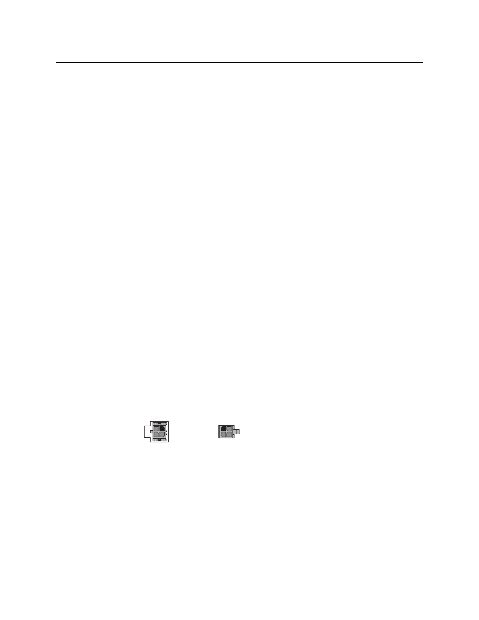
6 Connect one or both power supplies. First connect the 4-pin connector to PS1 or PS2 on the
rear of the router. The connectors are keyed and snap into place. There is only one way they
fit. Do not force them. Then connect the power supply to AC power.
The second power connection is for redundancy only (protection against failure) and is not a
requirement for operation.
7 Connect input devices and output devices. No particular order or combination is required.
Some of the MADI interfaces use standard 75
Ω BNC connectors.
Some of the MADI interfaces use DB25 connectors. You can obtain DB25 breakout cables
from Miranda or build your own cables. (The Miranda part number is WC0053. The sales
order code is NV5000-CABLE1.)
2
1
4
3
Receptacle
n.c.
n.c.
GND
12VDC
4
3
2
1
GND
12 VDC
n.c.
n.c.
Plug