Cr series compact routers installation, Software and documentation, Rotary switches – Grass Valley CR Series Quick Start v.3.2 User Manual
Page 4: Stand-alone routers, Stand-alone networks
4
Product Number: QG0003-13 Revision: 3.2; Date: 02 Dec 14
CR Series Compact Routers
Installation
Software and Documentation
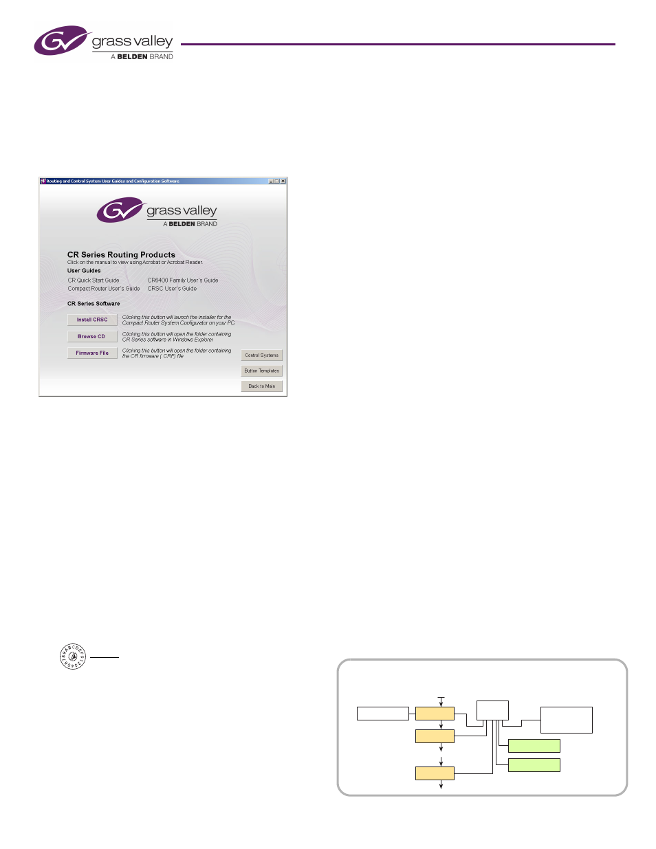
Insert the supplied CD (SB0033) in your CD drive. It will
autoplay in a few seconds. On the first screen you see, click
‘CR Series Routing Products’.
The CR Series screen displays:
You can choose from 4 options at any time:
•
Install CRSC.
•
Obtain documentation.
•
Open a button template.
•
Browse the CD.
To install the CRSC software, click ‘Install CRSC’ and follow
the simple steps when the installer appears. The installation
process takes less than a minute. Optionally, place a “short-
cut” on your PC desktop.
Rotary Switches
Every router and every remote panel module has a 16-posi-
tion rotary switch labeled ‘Frame ID’. CQX routers have an
additional rotary switch labeled ‘Mode’.
The ‘Frame ID’ rotary switch is used in stand-alone networks
(1) to set the device’s IP address and (2) for routers, to set the
router’s level.
It is used in CRSC networks, NV9000 networks, or CQX
(sub)networks to set a device’s initial IP address. You can use
CRSC to change IP addresses (and levels) to more suitable val-
ues once the routers and remote panel modules are in the net-
work. After initial setup, the rotary switch can be ignored.
Use a small screwdriver to make adjustments. Turn the switch
so that the arrow points to the setting number. The numbers
are in hexadecimal, where the letters A–F represent the num-
bers 10–15. (You might need to remove a control panel from
the router or remote panel module to access the rotary
switch.)
After you make an adjustment, turn the power to the router
(or remote panel module) on again.
If you set the rotary switch to position 0, the router or remote
panel module to reset to its factory default settings when you
cycle power. When you set the rotary switch to a non-zero
position, it retains its settings.
We recommend always setting a device to a non-zero position
while it is in use. Although it is possible to use device with a
zero switch setting, if you lose or remove power, it will reset
and lose its configuration.
Stand-Alone Routers
For a single router, you may set the rotary switch on the
router to any non-zero position.
Stand-Alone Networks
You may have up to 4 routers and up to 16 remote panel mod-
ules in a stand-alone network.
Set the rotary switches as follows.
For routers, the rotary switch sets both the router’s IP address
and the router’s level. For each router, choose a switch posi-
tion from 1 to 4:
Level (1–4) = switch setting.
Subnet address = switch setting + 100.
The IP address is 192.168.2.address. Thus, subnet addresses for
routers range from 101 to 104 and correspond to router levels
1–4. Each router’s rotary switch setting must be unique.
The switch settings of remote panel modules must also be
distinct. For each remote panel module, choose a switch posi-
tion from 0 to F:
Subnet address = switch setting + 50.
The IP address is 192.168.2.address. Thus, subnet addresses for
remote panel modules range from 50 to 65.
Routes and remote panels with switch position 0 will reset to the
factory default if power is removed.
FRAME ID
Position 0 is at the right.
Router
Ethernet
Switch
Config. PC
Remote Panel
Router
Router
Video Ref.
Remote Panel
Control Panel
optional
optional
Figure 2. Stand-Alone or CRSC Router Network