Switch reference – Grass Valley Performer-HD User Manual
Page 25
Performer-HD Instruction Manual
2-7
Dip Switch Configurations
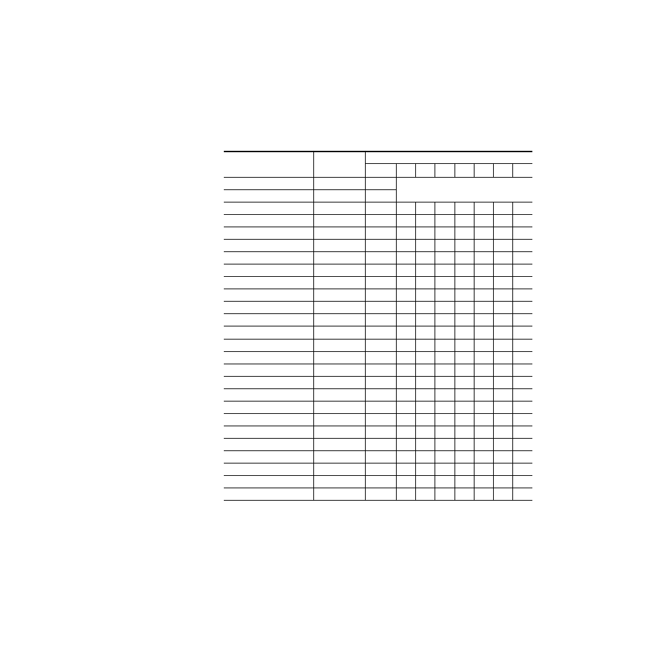
Switch Reference
lists potential settings and effects for dip switches used to config-
ure the Performer. Address and Starting Level default values are both zero
(0). O = an
open
or
OFF
switch segment; C = a
closed
or
ON
switch segment
.
Table 2-3.
Switch Reference, S1, 2, and 3 in Performer Switcher
Effect Switch
Segments
1
2
3
4
5
6
7
8
7 Data Bits
S3
C
Selectable for ASCII and Model 200 protocols
only. Other protocols are always 8 data bits.
8 Data Bits
S3
O
300 Baud
S3
O
O
O
`
600 Baud
S3
O
O
C
1200 Baud
S3
O
C
O
2400 Baud
S3
O
C
C
4800 Baud
S3
C
O
O
9600 Baud
S3
C
O
C
19.2K Baud
S3
C
C
O
38.4K Baud
S3
C
C
C
76.8K Baud
S3
O
O
O
No Parity
S3
O
O
Even Parity
S3
O
C
Odd Parity
S3
C
O
VI Internal, send external
S2
O
C
VI Internal, don’t send external
S2
O
O
VI S2
C
0
Address
a
a
Address values are cumulative and are added into the total when the switch is in the Closed (ON) position. De-
fault address offset is 000.
S1
128
64
32
16
8
4
2
1
10XL ASCII
S1
8
4
2
1
8
4
2
1
SMPTE 3245-E
S2
O
O
O
O
Perf ASCII
S2
O
O
O
C
100/110, Always
S2
O
C
O
O
100/110, Conditional
S2
O
C
O
C
Loopback Test
S2
C
C
O
O
Normal
S3
O
19 x 1 Secondary
S3
C