Rj45 to 5-pin din converter, Control bus structure, Maximum distance between ncb devices – Grass Valley TTN-BTS-3232/34 User Manual
Page 15: Control bus configuration notes
BTS-3232/34
Rev. 1
7
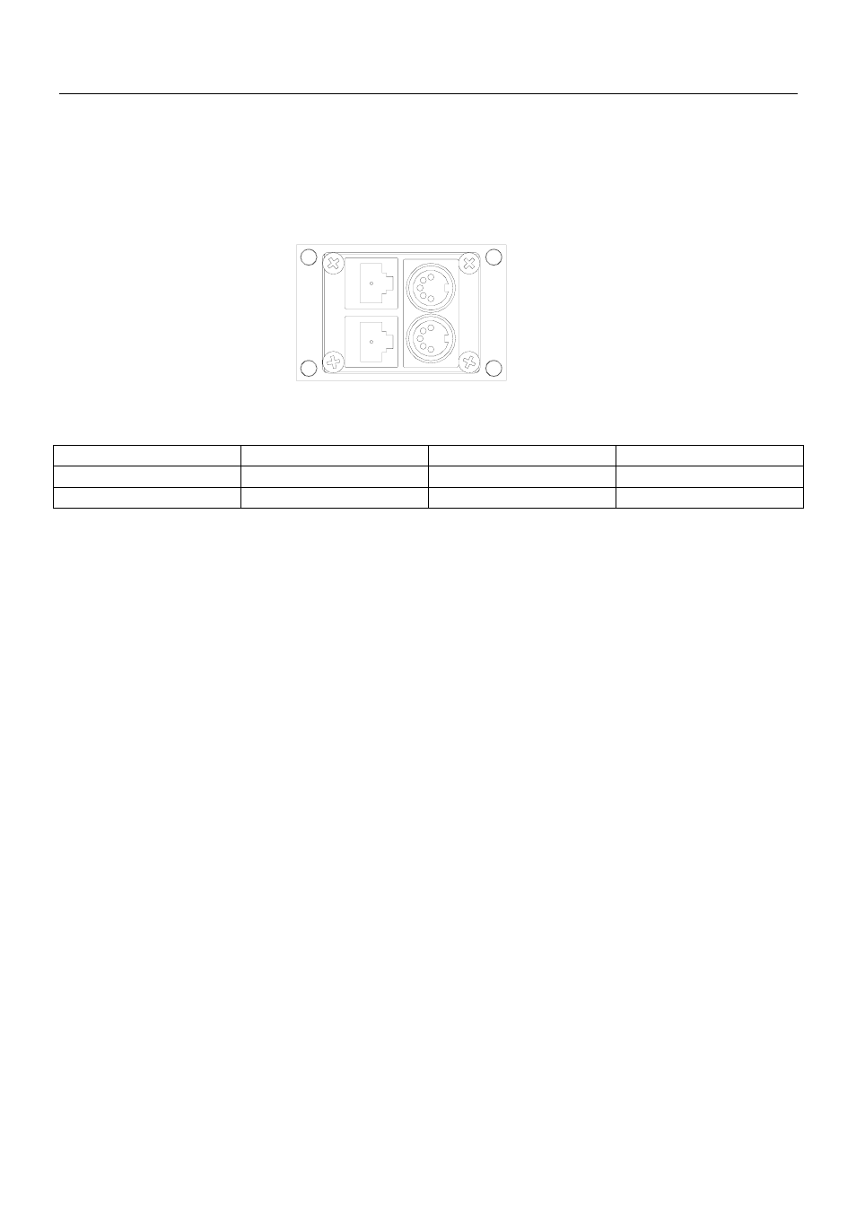
4.3.3 RJ45 to 5-pin DIN converter
In configurations that include both devices with RJ45 connectors, and devices with 5-pin DIN connectors,
an RJ45 to 5-pin DIN converter may be used to complete the control loop. This converter holds both
connector types, and may work both ways, thus from RJ45 to 5-pin DIN, as well as from 5-pin DIN to
RJ45.
The converter is connected as follows:
RJ45 (Router/CP)
RJ45 (Converter)
5-pin DIN (Converter) 5-pin DIN (Router/CP)
IN IN IN OUT
OUT OUT OUT IN
4.4 Control bus structure
The Network Control Bus structure follows the standard MIDI bus definition. The NCB is defined as a
closed chain of units. This means that the NCB OUT of the last unit must be connected to the NCB IN of
the first unit in the NCB chain. To avoid problems with the control of Triton units the installer/user has to
assure that the bus structure is installed according to this definition. The total number of Triton devices in
an NCB chain is limited to 20.
4.5 Maximum distance between NCB devices
The standard MIDI definition allows a maximum cable length of 250 meters between two devices.
Longer distances can be made with MIDI repeater units. To avoid grounding problems all NCB ports
have opto-coupled inputs.
4.6 Control Bus configuration notes
In order to achieve a system that is easy to maintain and control, follow the important notes, presented
hereunder.
•
Avoid using routers of different size, but same signal type (audio/video), on the same level.
Example: Do not configure a system with a BVS-1616 and a BTS-3232/34 on the same level. If
they were on the same level, crosspoint commands that were sent to the BVS-1616 lying outside
the range of the BTS-3232/34 would not be executed; the BTS-3232/34 would throw them off the
bus.
However, a combination of a BVS-1616 and an BAS-0808 will work well, because commands are
different for video- and audio routers.
•
Try to limit the number of devices on one Control Bus loop. If possible, separate systems that are
not to be controlled by one central control panel.
If you need to have several systems in one loop, try to separate as follows, using the DIP switches
on the rear of the devices:
o Analogue Video + Analogue Audio + CP for analogue system on Level 1
o SDI + AES/EBU + CP for digital system on Level 2