6 thr ead and under c ut cy cles – HEIDENHAIN SW 548328-05 User Manual
Page 263

HEIDENHAIN MANUALplus 620
263
4.6 Thr
ead and under
c
ut cy
cles
Type of machining for technology database access: thread cutting
Parameter combinations for the taper angle:
X1/Z1, X2/Z2
X1/Z1, Z2, W
Z1, X2/Z2, W
Cycle run
1
Calculate the proportioning of cuts
2
Move to thread starting point X1, Z1.
3
Move at the programmed feed rate to the contour end point Z2
4
Return on paraxial path and approach for next thread groove
5
Repeat 3 and 4 for all thread grooves
6
Approach for next pass, taking the reduced cutting depth and the
feed angle A
into account
7
Repeat 3 to 6 until no. threads D and depth U are reached
8
Move to the tool change point according to the G14 setting
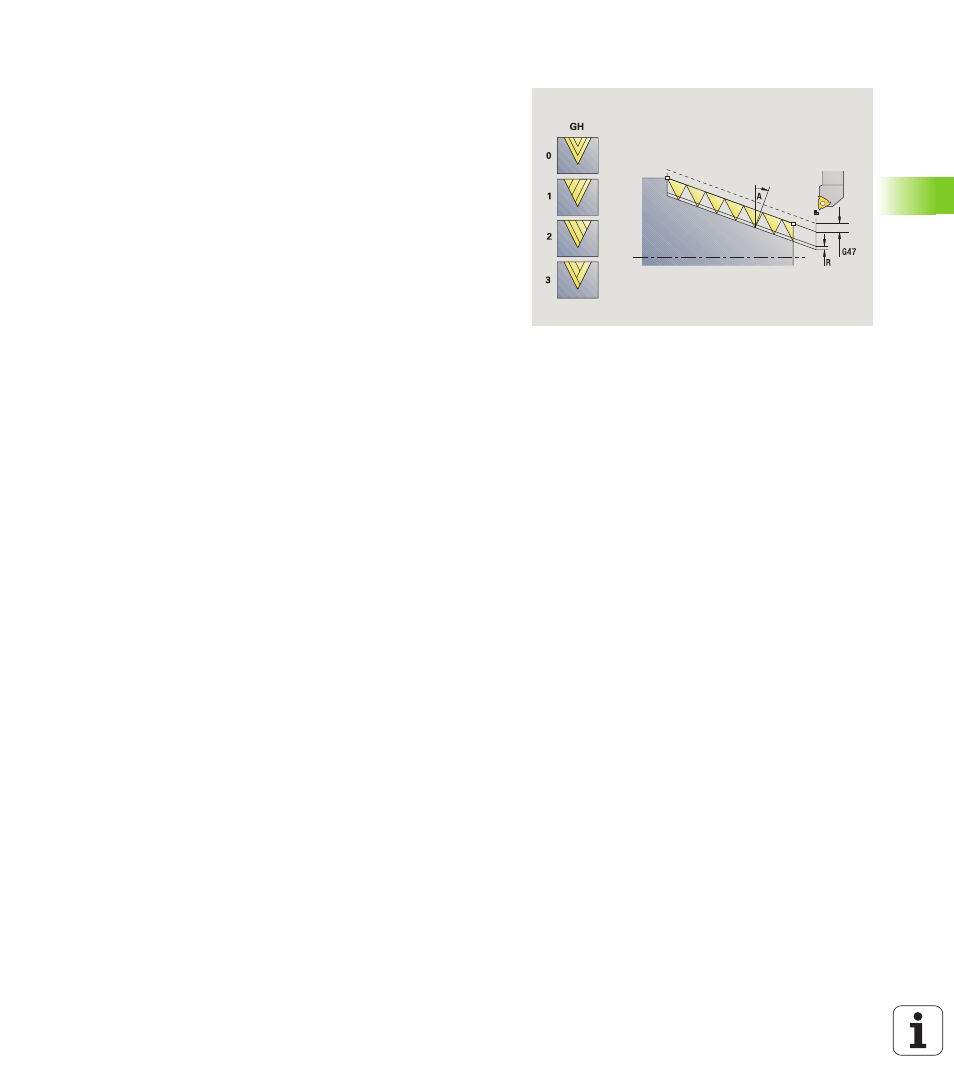
GH
Type of offset
0: Without offset
1: From left
2: From right
3: Alternately left/right
A
Approach (infeed) angle (range: –60° < A < 60°;
default 30°)
A<0: Infeed on left thread flank
A>0: Infeed on right thread flank
R
Remaining cutting depth only with GV=4 (default 1/100
mm)
E
Variable thread pitch (e.g. for manufacturing spiral
conveyors or extrusion shafts)
Q
No. no load (number of dry runs)
IC
Number of cuts—the infeed is calculated from IC and U.
Usable with:
GV=0: Constant chip cross section
GV=1: Constant infeed
MT
M after T: M function that is executed after the tool call T
MFS
M at beginning: M function that is executed at the
beginning of the machining step
MFE
M at end: M function that is executed at the end of the
machining step
WP
Displays which workpiece spindle is used to process the
cycle (machine-dependent)
Main drive
Opposing spindle for rear-face machining