Diagram d – ShoreLand'r SLB2313SW User Manual
Page 8
Midwest Industries, Inc.
Ida Grove, IA 51445
800.859.3028
www.shorelandr.com
0003397
Page 8
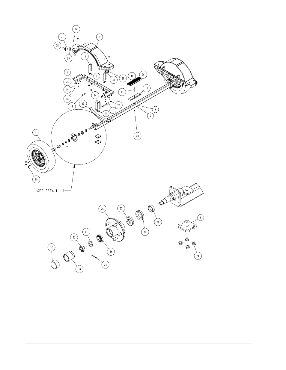
Diagram D
Tire Size and Carrying Capacity Chart
Tire Size ....................... ST185/80R 13-C
GVWR .......................... 2960 lb.
Carrying Capacity ....... 2300 lb.
Axle .............................. Non-Brake
Refer to the tire side wall for correct tire pressure.
SPRINGS
Position the axle so it is properly aligned with the
trailer. Place the springs on the top side of the
spring pads welded to the axle. (See chassis dia-
gram). Note that the hook end of the spring must
be mounted to the rear of the trailer. Place a spring
clamp on the top center of the spring as shown. Next
place the 1/2” x 6-1/2” U-bolts down over the top of
the spring clamp, spring and axle as shown.
Place the spring and axle U-bolt plate onto the ends of
the two U-bolts just placed. Secure in place with 1/2”
lock nuts. Thread onto the U-bolts but do not tighten
securely until the complete unit is in position on the
trailer. Repeat on the other spring.
Recommended carrying capacity is based on
shipping weight of the trailer with standard
equipment. Adding optional equipment may
decrease the trailer’s carrying capacity.