Diagram c – ShoreLand'r LUV30BSW V.2 User Manual
Page 5
Midwest Industries, Inc.
Ida Grove, IA 51445
800.859.3028
www.shorelandr.com
0003684
Page 5
08/18/06
the holes in it with the holes in the winch base.
Insert the two ½” and 1 ¼” carriage bolts into the holes just aligned
in the jack retainer plate and the winch base. Secure in place with
½” lock washers and hex nuts. Tighten.
Once tightened, rotate the jack through its normal pivoting range to
make sure it is free to travel and is not binding up.
If jack pivots, place it on the tongue and secure in place with the
bolts and hardware provided with the trailer. Complete the assem-
bly of the winch head to the winch base. Assembly is complete.
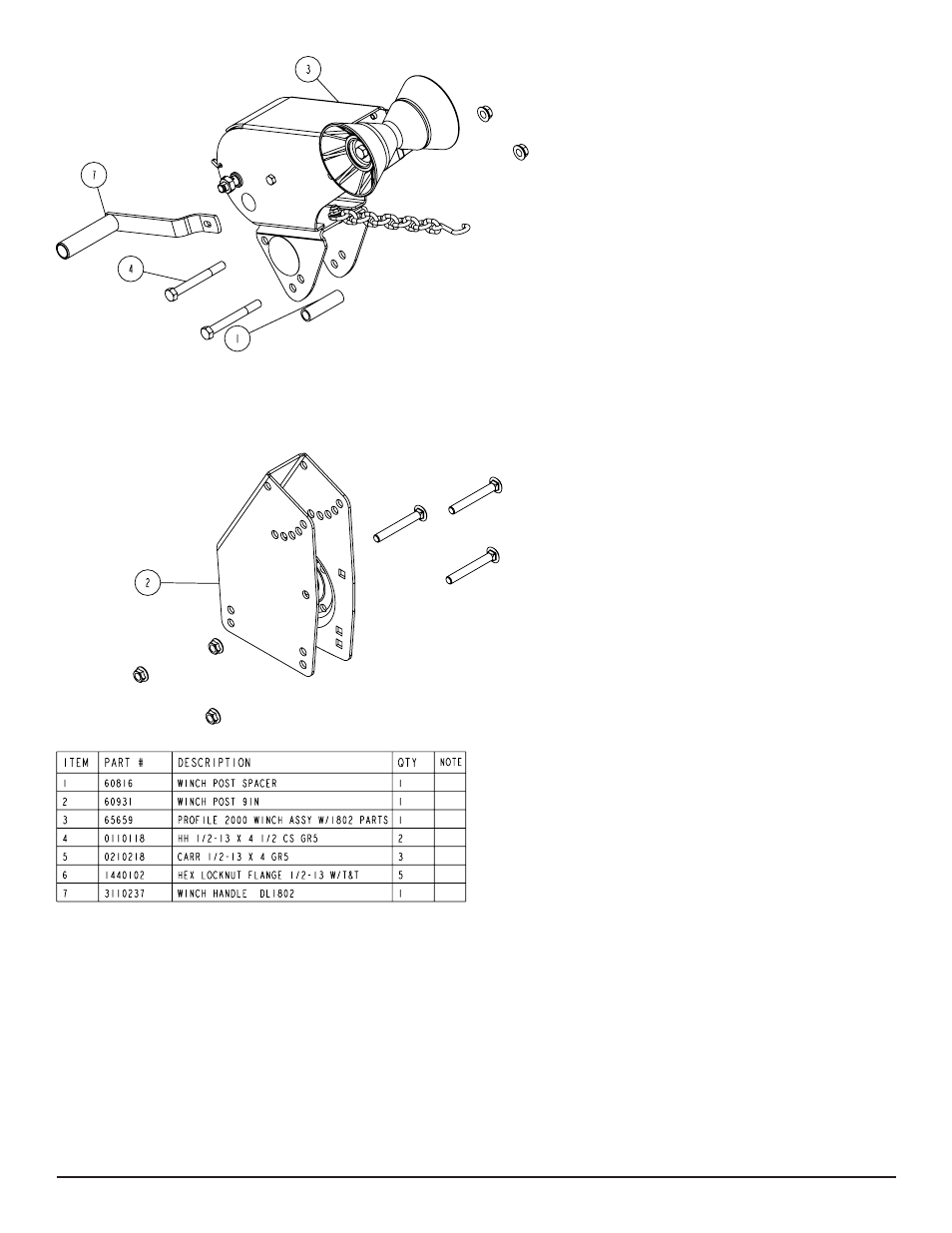
WINCH POST INSTALLATION
The height that the bow eye is placed in your boat will determine
the length winch post required. Once this is determined, attach the
winch base to the tongue with three 1/2” x 4-1/2” carriage bolts and
lock nuts.
Align the holes in the Profile 2000 mounting channel with the holes
in the top of the winch base. Attach the front of the winch head
mounting channel to the base by placing a 1/2” x 4-1/2” hex bolt
through the hole closest to the front of the winch base. Secure with
a lock nut. Do not tighten.
Note that the winch head can now be rotated either up or down.
Identify the correct hole combination to use to position the bow
eye roller just above the bow eye of your boat. When determined,
se¬cure in this position by placing the bushing as shown in Dia-
gram D inside the winch base so it aligns with the hole just identi-
fied for the proper adjustment. Insert another 1/2” x 4-1/2” hex bolt
through the determined mounting hole in the mounting channel and
winch base making sure the bolt passes through the bushing as
well. Secure with a 1/2” lock nut. Tighten all bolts.
Diagram C