Diagram b – ShoreLand'r SMB10TM V.2 User Manual
Page 5
Midwest Industries, Inc.
Ida Grove, IA 51445
800.859.3028
www.shorelandr.com
0003920
Page 5
01/25/2008
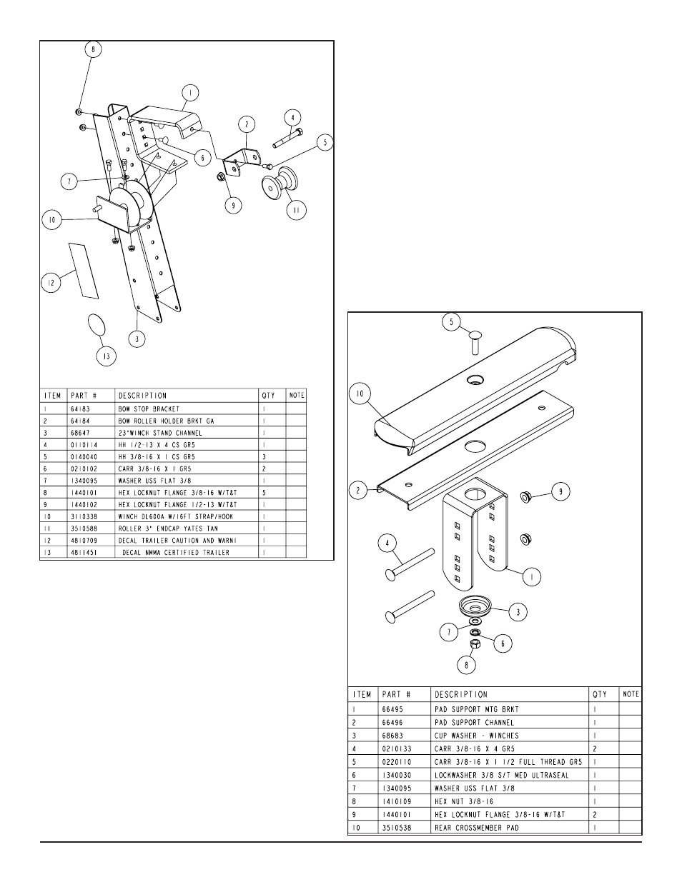
Diagram B
WINCH POST ASSEMBLY
The winch post assembly is pre-assembled and is shipped banded
to the frame. See Diagram B. Place the winch post on the tongue in
the approximate location. Attach to the tongue using three (3) 3/8”
x 4” hex bolts and 3/8” flange lock nuts. It can be left loose until the
boat is placed on the trailer for final adjustment.
Place the winch handle on the drive shaft of the winch by mating
the flat sides of the drive shaft with the punched hole in the winch
handle. Secure the handle to the drive shaft with the 1/2” lock nut
provided. Tighten.
BOW SUPPORT PAD ASSEMBLY
The TA0010 Bow Support Pad is used to add additional support to
the keel of your boat in the area over the tongue. It is adjustable
forward and backward as well as up and down. It can be raised to
the proper height to support your boat.
It also serves as a broader area for your boat to rest on, especially
a flat bottom boat when it is being loaded. Once loaded the boat
can be shifted to the center line of the keel rollers for proper sup-
port. At that time the bow support pad acts as an additional support
for the keel of the boat similar to a keel roller.
Locate the rear cross member pad (Item #10). Place it on the top
of the formed pad support channel. Drop the pad into the support
channel so that the center plastic ring of the pad fits in the hole of
the channel. Place the assembly onto the support mounting bracket
as shown. Attach the pieces together with a 3/8” X 1-1/2” carriage
bolt down from the top. Secure to the support mounting bracket by
first installing Item No. 3, cup washer and then a flat washer. Place
on a 3/8” lock washer and hex nut. Tighten.
The assembly is attached to the tongue with two 3/8” X 4” carriage
bolts, one on each the top and bottom side of the tongue. They are
secured in place with 3/8” flange lock nuts provided.
Note that the assembly is adjustable both up and down as well as
being able to be slid forward and backward on the tongue. Adjust
to its proper position. Secure in place by tightening the bolts just
installed. Assembly is complete.