4 basic configuration of the sunny island inverter – SMA Off-Grid Systems User Manual
Page 20
4 Single System
SMA Solar Technology AG
20
Off-Grid-IS-en-30
Installation - Quick Reference Guide
4.4 Basic Configuration of the Sunny Island Inverter
Requirements:
☐ The off-grid system must be installed according to the circuitry (see Section 4.1, page 17).
☐ All device enclosures must be closed except for the BatFuse. This protects all live components from being touched.
☐ All circuit breakers in the AC distribution board must be open. Thus, the Sunny Island is not connected to an AC
source.
Procedure:
C
SMACOM
Terminal RS485
2: Signal Data+ (A), color coding of the insulated conductor:
green with white stripes
5: Signal GND, color coding of the insulated conductor:
orange with white stripes
7: Signal Data − (B), color coding of the insulated conductor:
white with green stripes
/05*$&
Damage to the battery due to incorrect settings
The battery parameters influence the charging behavior of the Sunny Island inverter. The battery can be damaged by
incorrect settings of the parameters for battery type, nominal voltage, and capacity.
• Ensure that the values recommended by the battery manufacturer are set for the battery during basic configuration
(for the battery technical data, see the documentation of the battery manufacturer).
• In the basic configuration, configure the battery capacity for a ten-hour electric discharge (C10). The battery
manufacturer specifies the battery capacity in relation to discharge time.
Check the wiring
(see the Sunny Island inverter installation manual).
Close all devices except the BatFuse.
This protects all live components from being touched.
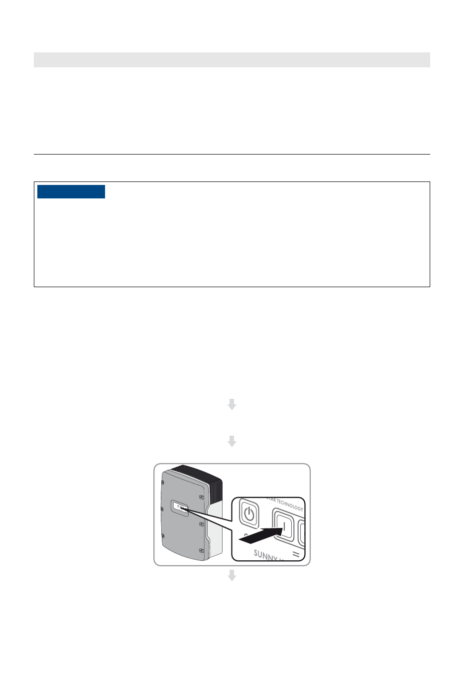
Close the BatFuse load-break switch and press the "On" button on the Sunny Island.
Position
Designation
Description/information