SMA SI-TB-BOX-10 User Manual
Page 38
6 Electrical Connection
SMA America, LLC
38
SI_TDBOX-IA-eng-IUS122211
Installation Manual
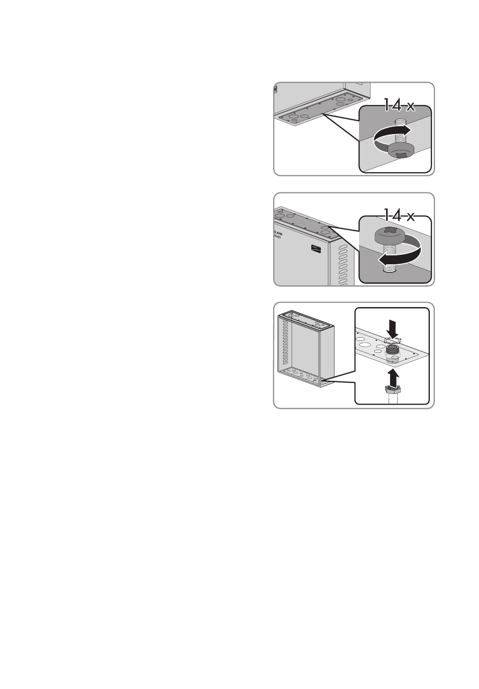
8. Insert the flange plates into the Smartformer:
• Hold the lower flange plate against the
Smartformer enclosure and tighten the
14 PZ 2 screws (torque: 25 in-lbs. (2.8 Nm)).
Use a torque wrench with a PZ 2 attachment or
another suitable cross-head screwdriver
attachment.
• Hold the upper flange plate against the
Smartformer enclosure and tighten the
14 PZ 2 screws (torque: 25 in-lbs. (2.8 Nm)).
Use a torque wrench with a PZ 2 attachment
or another suitable cross-head screwdriver
attachment.
9. Install the cable conduit between the Smartformer
and the components being connected.
10. Attach the conduit on the inside of the Smartformer
with a counter nut.
11. If a metal cable conduit is used, ground the cable conduit according to the locally applicable
standards and regulations. Tip: You can use a vacant terminal of the "Grounding" connecting
terminal plate to ground the conduit.
12. Insert the cable of the components being connected through the cable conduit into the
Smartformer.
13. If the cable is being introduced into the Smartformer from above, attach the cable with a cable
tie to one of the cable clamps. Use a cable length that reaches to the specified terminal.
14. Make sure that all opened knockouts are closed again.