SMA MC-Box 6.3 User Manual
Page 23
SMA Solar Technology AG
6 Electrical Connection
Operating Manual
MC-BOX-6_12-BE-en-20
23
6.1.4 Bottom View of the Multicluster Box 12.3 (without Base)
Object
Description
A
RJ45 pin connectors for connecting the data cables for control and measuring
signals
B
RJ45 pin connector for connecting the data cable for communication
C
Cable support rail for strain relief of the cables
D
Fuse switch-disconnector F1 Generator for connecting the generator (L1, L2, L3)
E
Terminals X1 Generator for connecting the generator (N, grounding conductor)
F
Fuse switch-disconnector F2 Loads for connecting the loads (L1, L2, L3)
G
Terminals X2 Loads for connecting the loads (N, grounding conductor)
H
Terminals X3 PV-System for connecting the PV system
(L1, L2, L3, N, grounding conductor)
I
Circuit breaker for connecting the Sunny Island inverters (L)
J
Terminals X4 All Clusters for connecting the Sunny Island inverters
(N, grounding conductor)
K
Terminal X5 Equipotential Busbar for connecting the grounding conductor
(for grounding the entire multicluster system)
Object
Description
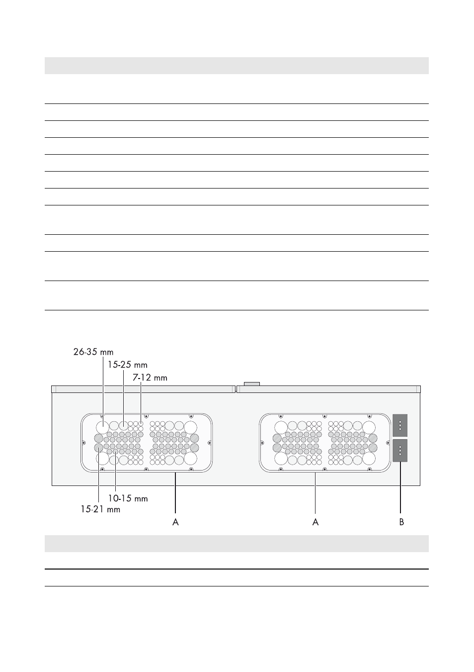
A
Flange plate with membranes for inserting the connection cables
B
Two-part cable feed-through for inserting the data cables