SMA Funksteckdose mit BLUETOOTH Wireless Technology User Manual
SMA Equipment
BTFSD-IA-en-es-it-13 | Version / Versión / Versione 1.3
SMA Solar Technology AG
SMA Radio-Controlled Socket
with BLUETOOTH
®
Wireless Technology
Installation manual
The SMA radio-controlled socket is
1. an accessory to the Sunny Home Manager.
2. a repeater for devices with SMA BLUETOOTH
®
Wireless Technology.
The SMA radio-controlled socket must only be used in
accordance with this document or the manuals for the
Sunny Home Manager. Any other use may result in
personal injury or property damage.
Any use of the product other than that described in the
Intended Use section does not qualify as appropriate.
It is prohibited to make modifications that are not ap-
proved by SMA Solar Technology AG.
This document is valid for device type "BT-SOCKET-
10" as of firmware version 1.00.0.R (see type label).
This document is intended for end users and skilled
persons. Some of the tasks described in this document
may only be performed by skilled persons with the
appropriate qualifications. These tasks are identified
by an information note. Skilled persons must have the
following qualifications:
• Training in the installation and commissioning of
electrical devices.
• Knowledge of the applicable standards and
guidelines
The enclosed documentation is an integral part of this
product.
• The documentation must be read, observed and
always kept in a convenient place for future
reference.
The SMA radio-controlled socket is approved for the
use in all EU member states. The SMA radio-controlled
socket is designed for indoor use only.
• Only connect the SMA radio-controlled socket to
easily accessible outlets.
• Only connect the SMA radio-controlled socket to
properly installed socket-outlets with a grounding
contact.
• Only connect loads to the SMA radio-controlled
socket which are suitable for its voltage and power
range.
Danger to life due to electric shock
Lethal voltages are present in the conductive
components.
• Only use the SMA radio-controlled socket in a dry
environment.
• Avoid any influence of moisture and dust as well as
of solar irradiation and any other thermal irradiati-
on.
• Only insert suitable plugs in the
SMA radio-controlled socket.
• Before cleaning, pull the SMA radio-controlled so-
cket out of the socket-outlet, and clean with a dry
cloth only.
The SMA radio-controlled socket is equipped with a
relay with μ contact.
• Remove the SMA radio-controlled socket from the
electricity grid for safe disconnection.
Risk of inadvertent switching
The SMA radio-controlled socket used in conjunction
with the Sunny Home Manager can be switched via
the Sunny Portal (see manuals for the Sunny Home
Manager).
• Do not connect any loads. e.g. iron, to the SMA ra-
dio-controlled socket which could endanger per-
sons or cause damage if inadvertently switched on.
Damage to the SMA Radio-Controlled Socket
If the SMA radio-controlled socket is not operated pro-
perly, it could be damaged.
• Do not operate SMA radio-controlled sockets
when they are plugged into each other.
Check the delivery for completeness and any visible
external damage.
• 1 x SMA radio-controlled socket
• 1 x installation manual
• 1 x supplementary sheet
Upper horizontal LED:
• Glowing green: SMA radio-controlled socket is
switched on. Load can draw electricity.
• Glowing orange: SMA radio-controlled socket is
switched off. Load cannot draw electricity.
• Glowing red: system is in the start-up or update
phase. Do not pull the SMA radio-controlled
socket out of the socket-outlet. Otherwise, the
SMA radio-controlled socket could be damaged.
Lower horizontal LED:
• Glowing blue: good SMA BLUETOOTH connec-
tion
• Flashing blue: critical SMA BLUETOOTH connec-
tion
Vertical LEDs:
• Glowing green: touch key is ready for operation.
Establishing the default settings is possible
(see Section "Establishing the default settings").
• Flashing green: SMA radio-controlled socket is
initializing.
☐ Socket-outlet is located in a suitable position
between devices with critical signal quality.
☐ A minimum distance of 1m to devices using the 2.4
GHz frequency band (e.g. WLAN devices,
microwave ovens) is observed.
1. Decommission the plant (see manuals of the
connected devices). This will ensure that the
SMA radio-controlled socket is integrated into the
SMA BLUETOOTH network at the point where the
dead zone occurs.
2. Insert the SMA radio-controlled socket into the soc-
ket-outlet.
☑ Upper horizontal LED (A) glows red for approx.
10 seconds.
3. As soon as the LED display shows "0", tap the
touch key (B) several times until the NetID of the
plant is displayed.
4. Wait five seconds to adopt the NetID.
5. Recommission the plant (see the manuals of the
connected devices).
☑ Wait approx. two minutes until the lower
horizontal LED is glowing blue.
✖ If the lower horizontal LED is flashing blue:
SMA BLUETOOTH connection is critical.
• If possible, move to another installation site.
• If no other installation location is possible, use
an additional SMA radio-controlled socket or
an SMA BLUETOOTH Repeater.
✖ If the lower horizontal LED is off:
No SMA BLUETOOTH connection.
• Make sure that the SMA radio-controlled
socket and the plant devices are set to the same
NetID (see Section "Change NetID").
• If possible, move to another installation site.
• If no other installation location is possible, use
an additional SMA radio-controlled socket or
an SMA BLUETOOTH Repeater.
1. Keep the touch key pressed until the LED display
shows the previously set NetID.
2. Tap the touch key several times until the desired
NetID is displayed.
3. Wait five seconds to adopt the NetID.
1. Pull out and reinsert the SMA radio-controlled so-
cket into the socket-outlet.
☑ Upper horizontal LED glows red for approximately
ten seconds.
2. As soon as the vertical LEDs are glowing green,
keep the touch key pressed until the upper horizon-
tal LED is glowing red.
☑ LED display shows "0".
1. To switch on the SMA radio-controlled socket, tap
the touch key.
☑ Upper horizontal LED is glowing green.
The SMA radio-controlled socket audibly
switches to the selected operating mode.
2. To switch off the SMA radio-controlled socket, tap
the touch key.
☑ Upper horizontal LED is glowing orange.
The SMA radio-controlled socket audibly switches
to the selected operating mode.
Enchufe inalámbrico de SMA
con BLUETOOTH
®
Wireless Technology
Instrucciones de instalación
El enchufe inalámbrico de SMA:
1. Es un accesorio del Sunny Home Manager.
2. Es un repetidor entre los equipos con
SMA BLUETOOTH
®
Wireless Technology.
Utilice el enchufe inalámbrico de SMA únicamente
siguiendo las indicaciones de este documento o las
instrucciones del Sunny Home Manager. Otros usos
del producto pueden causar lesiones al usuario o
daños materiales.
Cualquier uso del producto distinto al descrito en el
uso previsto se considerará uso inadecuado.
Quedan
prohibidas las modificaciones o incorporaciones no
autorizadas.
Este documento es válido para el tipo de equipo
“BT-SOCKET-10” a partir de la versión de firmware
1.00.00.R (consulte la placa de características).
Este documento está dirigido a usuarios finales y espe-
cialistas. Algunas de las actividades descritas en este
documento solo podrá llevarlas a cabo personal
especializado con la cualificación correspondiente.
Estas actividades están señalizadas mediante una
indicación. El personal especializado debe contar
con esta cualificación:
• Formación para la instalación y puesta en servicio
de equipos eléctricos
• Conocimientos de las normativas y directrices
aplicables
La documentación adjunta es parte integrante del
producto.
• Lea y tenga en cuenta esta documentación y
consérvela en un lugar de fácil acceso en todo
momento.
El enchufe inalámbrico de SMA está homologado
para todos los países de la UE. El enchufe inalámbrico
de SMA es apto únicamente para su uso en interiores.
• Conecte el enchufe inalámbrico de SMA solamen-
te en tomas de pared fácilmente accesibles.
• Conecte el enchufe inalámbrico de SMA solamen-
te en tomas de pared instaladas conforme a la
normativa y con toma de tierra.
• Al enchufe inalámbrico de SMA conecte
únicamente equipos consumidores adecuados
para el rango de tensión y de potencia del enchu-
fe inalámbrico de SMA.
Peligro de muerte por descarga eléctrica
En los componentes conductores de tensión hay
tensiones eléctricas que pueden causar la muerte.
• Utilice el enchufe inalámbrico de SMA únicamente
en entornos secos.
• Evite la influencia de humedad y polvo así como la
radiación solar o térmica.
• Conecte en el enchufe inalámbrico de SMA
únicamente tomas adecuadas.
• Desenchufe el enchufe inalámbrico de SMA de la
toma de la pared antes de limpiarlo y límpielo solo
con un paño seco.
El enchufe inalámbrico de SMA tiene un relé con un
contacto μ.
• Para llevar a cabo una desconexión de la red
pública de manera segura, retire el enchufe
inalámbrico de SMA de la toma de pared.
Peligro por conexión involuntaria
El enchufe inalámbrico de SMA puede accionarse
conectado con un Sunny Home Manager a través del
Sunny Portal (consulte las instrucciones del
Sunny Home Manager).
• No conecte al enchufe inalámbrico de SMA
ningún equipo consumidor que pueda provocar
daños personales o materiales por una conexión
involuntaria (p. ej., la plancha).
Daños en el enchufe inalámbrico de SMA
Si se lleva a cabo un uso inadecuado, el enchufe
inalámbrico de SMA podría dañarse.
• No conecte los enchufes inalámbricos de SMA
entre sí.
Compruebe que el contenido de la entrega esté
completo y que no presente daños externos visibles.
• Un enchufe inalámbrico de SMA
• Unas instrucciones de instalación
• Un suplemento
Led superior horizontal:
• Verde encendido: el enchufe inalámbrico de SMA
está conectado. El equipo consumidor puede
tomar corriente.
• Naranja encendido: el enchufe inalámbrico de
SMA está desconectado. El equipo consumidor no
puede tomar corriente.
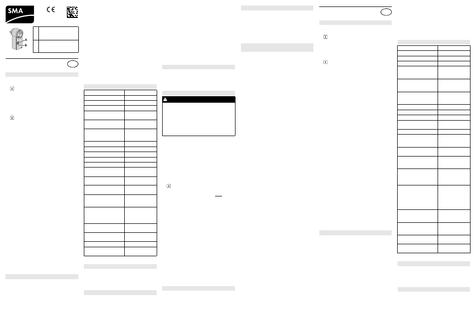
A LED display/
Indicador led/
Segnalazioni dei LED
B Touch key/
Tecla del sensor/
Tasto sensore
Intended Use
Control via Sunny Home Manager
For instructions on how to control the SMA
radio-controlled socket via the
Sunny Home Manager, refer to the manuals of
the Sunny Home Manager only.
Use as a repeater
This document exclusively applies to the
use of the SMA radio-controlled socket as
a repeater.
Safety Precautions
961.187
EN
Technical Data
Input voltage
100 V
AC
to 230 V
AC
Frequency
50 Hz / 60 Hz
Maximum current
16 A
Current consumption
0.25 W to 1.5 W
Max. switching power with
resistive load
3,680 W
Max. switching power with
lamp load
600 W
Max. switching power with
inductive load
(cos φ > 0.65)
1,200 VA
Ambient temperature
− 5°C to +35°C
Relative humidity*
* non-condensing
5% to 95%
Degree of protection**
** in accordance with IEC 60529
IP20
Max. altitude above MSL
3,000 m
Pollution degree
2
Rated value of impulse with-
stand voltage
2,500 V
Operating mode of the elec-
tronic switch
S1
Type and/or circuitry of the
switch
1 pole, 1 load (1-pole
disconnection)
Used in electric circuits for a
inductive load with a power
factor of at least 0.6
Yes
Used in electric circuits for a
specified motor load with a
blocked rotor and a power
factor of at least 0.6
Yes
Comparative figure for proof
tracking index
PTI 175
Glow wire test (GWT) tem-
perature
850°C
Forced cooling required
No
Installed protective devices
present
No
Scope of Delivery
LED States
Requirements for the Installation Site
Commissioning
DANGER
Risk of lethal electric shock when touching
conductive components of the inverter
• Only skilled persons may work on the
inverter.
• Prior to performing any work on the inverter,
disconnect the inverter from any voltage
sources on the AC and DC sides (see inverter
installation manual).
The same NetID for all devices
All SMA devices communicating via
BLUETOOTH must be set to the same NetID.
The NetID can be a number from 2 to 9 or a let-
ter from A to F.
Changing the NetID
Establishing the Default Settings
Switching on/off the SMA radio-controlled
socket
Uso previsto
Control del Sunny Home Manager
Para el control del Sunny Home Manager ten-
ga en cuenta únicamente las instrucciones del
Sunny Home Manager.
Utilización como repetidor (“repeater”)
Este documento sirve exclusivamente
para
la
aplicación
del
enchufe
inalámbrico de SMA como repetidor.
Indicaciones de seguridad
ES
Datos técnicos
Tensión de entrada
100 V
CA
… 230 V
CA
Frecuencia
50 Hz/60 Hz
Corriente máxima
16 A
Consumo de electricidad
0,25 W … 1,5 W
Potencia máxima de
conmutación con carga re-
sistiva
3 680 W
Potencia máxima de
conmutación con carga de
lámpara
600 W
Potencia máxima de
conmutación con carga in-
ductiva (cos φ > 0,65)
1 200 VA
Temperatura ambiente
− 5 °C … +35 °C
Humedad relativa del aire*
* Sin condensación
5% … 95%
Tipo de protección**
** Según IEC 60529
IP20
Altitud máx. sobre el nivel
del mar
3 000 m
Índice de contaminación
2
Valor de medición de la
tensión de choque soporta-
ble
2 500 V
Tipo de funcionamiento del
interruptor electrónico
S1
Tipo y/o conmutación del in-
terruptor
Un polo, una carga
(desconexión unipo-
lar)
Aplicación en circuitos
eléctricos para una carga in-
ductiva con un factor de po-
tencia de al menos 0,6
Sí
Aplicación en circuitos
eléctricos para una carga
del motor determinada con
un rotor bloqueado y con un
factor de potencia de al
menos 0,6
Sí
Índice de resistencia a la
formación de caminos con-
ductores
PTI 175
Temperatura de la prueba
del hilo incandescente
(GWT)
850 °C
Refrigeración forzada nece-
saria
No
Disponible dispositivo de
protección integrado
No
Contenido de la entrega
Estados de led