SMA CLUSTER CONTROLLER Installation User Manual
Page 69
Requirements:
☐ The remote terminal must be technically suitable for connection to the digital outputs (see
☐ The connection cable must be prepared for connection to the multipole plug (see Section 6.5,
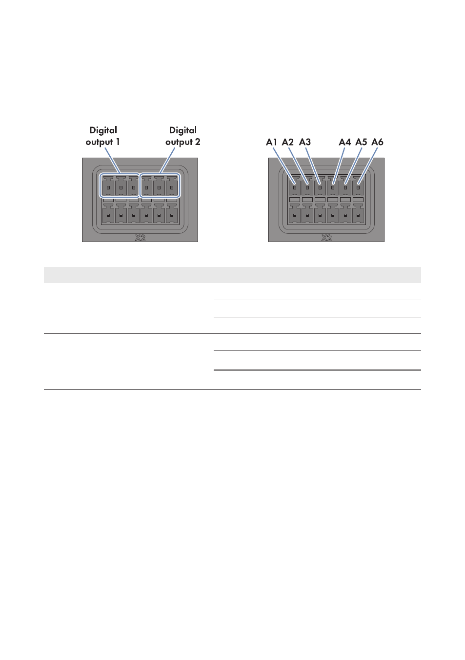
Figure 32: Pin assignment for the pin groups Digital output 1 and Digital output 2
Pin group
Relay
Pin
Signal
Explanation
Digital output 1
Fault indicator contact for
the system status Error
A
A1
NC
Back contact
A2
CO
Change-over contact
A3
NO
Front contact
Digital output 2
Fault indicator contact for
the system status Error or
Warning
B
A4
NC
Back contact
A5
CO
Change-over contact
A6
NO
Front contact
Procedure:
1. Connect the connection cable to the remote terminal (see the manual from manufacturer). Trim
the unneeded insulated conductors up to the cable shield and note down the conductor colors.
2. Connect the connection cable to the six-pole plug:
• Depending on the remote terminal and the pin assignment of the desired pin group,
identify the conductor entries that are required for connecting the connection cable.
• Release the required conductor entries using a screwdriver and insert the insulated
conductors into the conductor entries. Observe the pin assignment.
3. Insert the six-pole plug into pin row A in terminal X2.
4. On the connection cable, mark the terminal and the pin row to which the connection cable is
assigned. Use the supplied cable tie with caption field.
5. Write down the terminal assignment on the supplied supplementary sheet.
6 Connection and Commissioning
SMA Solar Technology AG / SMA America, LLC
Installation Manual
69
ClusterController-IA-en-14