0 configuring the function blocks, Source operation drive – Yaskawa G5 Eliminator User Manual
Page 5
Date: 07/01/04, Rev: 04-07
Page 5 of 27
TM.G5SW.015
1.0 Configuring The Function Blocks
User Configurable software allows the GPD515/G5 drive to be configured to a specific
application. This is accomplished by internal drive functions that may be connected to provide
the logic required. For the purposes of understanding and developing logic the internal
functions have been reduced to function blocks. The function block diagrams indicate how they
can be connected.
Some functions have required setup as multi-function selections to operate. Many functions
have associated parameters to provide control. Developing a configuration involves choosing
the functions required, connecting them for the required logic and setting the parameters that
control the functions.
1.1
Developing a Configuration
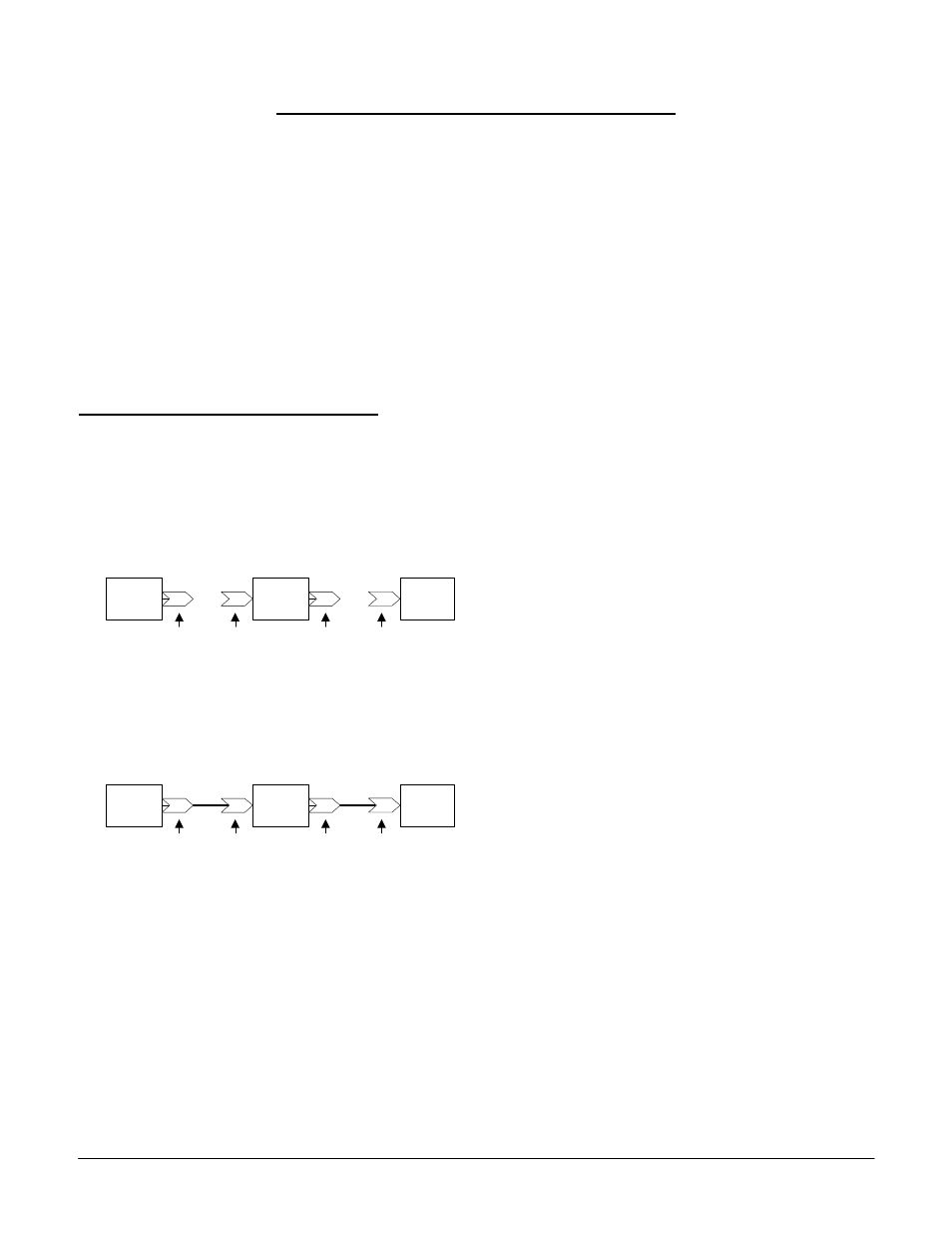
Function blocks are simple block diagrams that indicate their function and how they are
connected. The arrow like icons used for the input and output connectors indicate the direction
information is moving. A connector number is shown within these icons. Figure 1.1 shows the
anatomy of the three categories of functions as function blocks.
Using function blocks provides a way to develop configurations so they may be understood.
From Figure 1.1 it is possible to see how the function blocks may be connected. Figure 1.2
demonstrates how the function blocks are connected.
In figure 1.2 a source input function sends information to the output connector 01. The
information is passed through the connection to the input connector 02 of the operation. The
operation reads this information and converts it sending the result to the output connector 03.
The information is passed through the connection to the input connector 04. The drive output
function directs the information to control the drive. All configurations follow this example.
There can be more complex configurations with more operations but the basics are the same.
The information starts at a source. It is connected to the operations necessary to convert and
control it. The information is then passed to the drive.
Developing a configuration for a drive requires selecting a data source and directing it through
operations changing it to information that will provide the proper drive control and then
Output
Connector
Input
Connector
Figure 1.1
Source
Input
Function
#
Convert
Source
Function
#
#
Drive
Output
Function
#
Output
Connector
Input
Connector
Source
Operation
Drive
Output
Connector
Input
Connector
Figure 1.2
Source
Input
Function
01
Convert
Source
Function
03
02
Drive
Output
Function
04
Output
Connector
Input
Connector
Source
Operation
Drive
Connection
Connection