Yaskawa G5 Output Voltage PID User Manual
Output voltage pid, Application, Simplified software block diagram
Date: 07/01/04, Rev: 04-07
Page 1 of 6
TM.G5SW.022
Output Voltage PID
Document Name
TM.G5SW.022
Document Revised
07/01/04
Software Number
VSG114771
Software Revised
07/10/2001
This software will convert a Yaskawa
GPD515/G5 inverter into a VDC to VAC
converter with the ability to control the
frequency and the voltage of the VAC output.
The frequency can be set via the normal
frequency reference methods. The VAC output
can be controlled by a voltage set point signal
and regulated via a PID utilizing a voltage
feedback signal. The E1-05 constant may be
used to set the minimum voltage output. A filter
network can be used to cleanup the pulse width
modulated output.
The PID algorithm is a duplicate of the one used
in standard software with minor modifications.
The Auxiliary PID constants function in the
same manner as the B5 PID constants.
This document is an addendum to Technical
Manual TM4515, listing the effect of this
software on the parameters in the drive and
function descriptions in the manual.
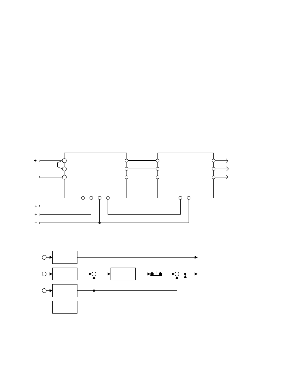
Application
Simplified Software Block Diagram
Frequency Reference (0-10V)
U (T1)
W (T3)
V (T2)
13
14
(cut
J1)
17
(C
om
mon)
16
GPD515/G5
Inverter
Filter & Regulator
Network
L1
0 to 10 VDC
+
com
-
+ 2
+ 1
VDC
L1
L2
L3
Voltage Setpoint (0-10V)
Common
Voltage Regulator Feedback (0-10V)
Common
L2
L3
Frequency Output
Voltage Output
Frequency
Reference
13
Voltage
Feedback
Voltage
Setpoint
14
16
+
-
P1-01 = 1,2
Enabled
PID
+
+
E1-05
Max Voltage